Integrated I/O connectors and signals
A-11
014–002250–01
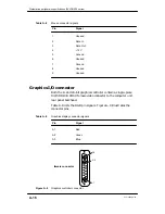
SCSI–2 expansion bus connectors
Each expansion SCSI controller contains two rear panel bus
connectors. Systems may include one to four expansion SCSI buses.
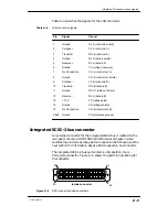
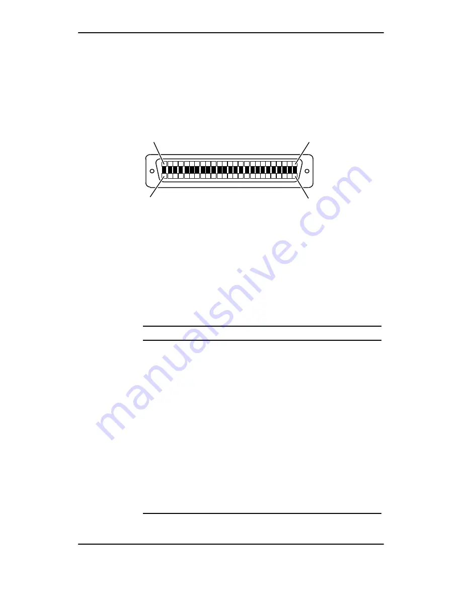
The rear panel expansion SCSI–2 bus ports contain 68–position,
male P&S–style connectors. Figure A–5 shows the position
numbering for the SCSI expansion connectors.
34
female connector
68
1
35
Figure A–6
SCSI expansion bus connector position numbers
The SCSI bus standard describes two types of pin assignments: one
for devices that use single–ended drivers and another for devices
that use differential drivers. Your expansion buses may be
configured for either singled–ended or differential operation.
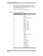
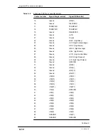
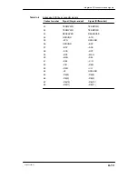
Table A–6 lists both the single–ended and differential connector
signals for AViiON 5500 and 550 series expansion buses.
Table A–6
Expansion SCSI bus connector signals
Contact number
Signal (Single–ended)
Signal (Differential)
1
Ground
+DB(12)
2
Ground
+DB(13)
3
Ground
+DB(14)
4
Ground
+DB(15)
5
Ground
+DB(P1)
6
Ground
GROUND
7
Ground
+DB(0)
8
Ground
+DB(1)
9
Ground
+DB(2)
10
Ground
+DB(3)
11
Ground
+DB(4)
12
Ground
+DB(5)
13
Ground
+DB(6)
14
Ground
+DB(7)
Continued
Summary of Contents for AViiON 550 Series
Page 2: ......
Page 6: ......
Page 12: ...Joining our users group x 014 002250 01 ...
Page 86: ...Opening and closing the computer unit 4 12 014 002250 01 ...
Page 96: ...Installing a drive assembly 5 10 014 002250 01 ...
Page 188: ......
Page 191: ......


