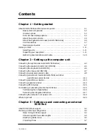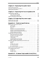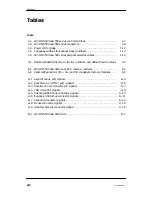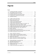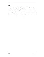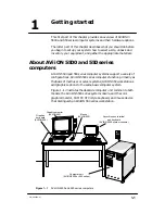
Contents
xvii
014–002250–01
Figure
8–1
AViiON 5500 and 550 series system board and mounted components
. . .
8–2
Unplugging cables from the system board
. . . . . . . . . . . . . . . . . . . . . . . . . . . .
8–3
Unscrewing the main system board screws
. . . . . . . . . . . . . . . . . . . . . . . . . . .
8–4
Dislodging the system board from the computer chassis
. . . . . . . . . . . . . . .
8–5
Removing the system board
. . . . . . . . . . . . . . . . . . . . . . . . . . . . . . . . . . . . . . . . .
8–6
Removing the System ID PROM component
. . . . . . . . . . . . . . . . . . . . . . . . . .
8–7
Straightening the pins on the PROM component
. . . . . . . . . . . . . . . . . . . . . .
8–8
Installing the System ID PROM component
. . . . . . . . . . . . . . . . . . . . . . . . . .
8–9
Location of AViiON 5500 and 550 series system board jumpers
. . . . . . . . .
8–10 Configuring the synchronous operation jumpers
. . . . . . . . . . . . . . . . . . . . . .
8–11 Aligning the system board before installing
. . . . . . . . . . . . . . . . . . . . . . . . . .
8–12 Inserting the system board in the computer unit
. . . . . . . . . . . . . . . . . . . . . .
8–13 Securing the system board to the computer unit
. . . . . . . . . . . . . . . . . . . . . .
8–14 Securing additional system board screws
. . . . . . . . . . . . . . . . . . . . . . . . . . . .
8–15 Plugging cables into the system board
. . . . . . . . . . . . . . . . . . . . . . . . . . . . . . .
9–1 Removing the fan assembly power cable
. . . . . . . . . . . . . . . . . . . . . . . . . . . . .
9–2 Releasing the fan assembly from the computer unit
. . . . . . . . . . . . . . . . . . .
9–3 Installing the fan assembly
. . . . . . . . . . . . . . . . . . . . . . . . . . . . . . . . . . . . . . . . .
9–4 Plugging the fan assembly power cable into the power supply
. . . . . . . . . .
9–5 Removing the front panel LED
. . . . . . . . . . . . . . . . . . . . . . . . . . . . . . . . . . . . . .
9–6 Removing the speaker
. . . . . . . . . . . . . . . . . . . . . . . . . . . . . . . . . . . . . . . . . . . . . .
9–7 Disconnecting the fan assembly power cable
. . . . . . . . . . . . . . . . . . . . . . . . . .
9–8 Disconnecting the fan assembly power cable and removing the connector
9–9 Unplugging the speaker/LED/fan power supply cable
from the system board
. . . . . . . . . . . . . . . . . . . . . . . . . . . . . . . . . . . . . . . . .
10–1 Unplugging the system board ac power power cables
. . . . . . . . . . . . . . . . . .
10–2 Releasing the disk and tape power connectors
. . . . . . . . . . . . . . . . . . . . . . . .
10–3 Disconnecting the front panel power switch assembly
. . . . . . . . . . . . . . . . .
10–4 Removing the power supply screws from the computer unit rear panel
. .
10–5 Securing the power supply to the computer unit
. . . . . . . . . . . . . . . . . . . . . .
10–6 Connecting the disk and tape power connectors
. . . . . . . . . . . . . . . . . . . . . . .
10–7 Connecting the system board ac power cables
. . . . . . . . . . . . . . . . . . . . . . . .
10–8 Connecting the front panel power switch assembly
. . . . . . . . . . . . . . . . . . . .
Summary of Contents for AViiON 550 Series
Page 2: ......
Page 6: ......
Page 12: ...Joining our users group x 014 002250 01 ...
Page 86: ...Opening and closing the computer unit 4 12 014 002250 01 ...
Page 96: ...Installing a drive assembly 5 10 014 002250 01 ...
Page 188: ......
Page 191: ......

