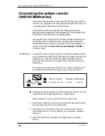
Connecting the graphics monitor (AViiON 550)
2-5
014–002250–01
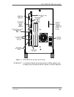
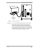
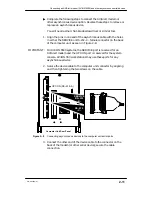
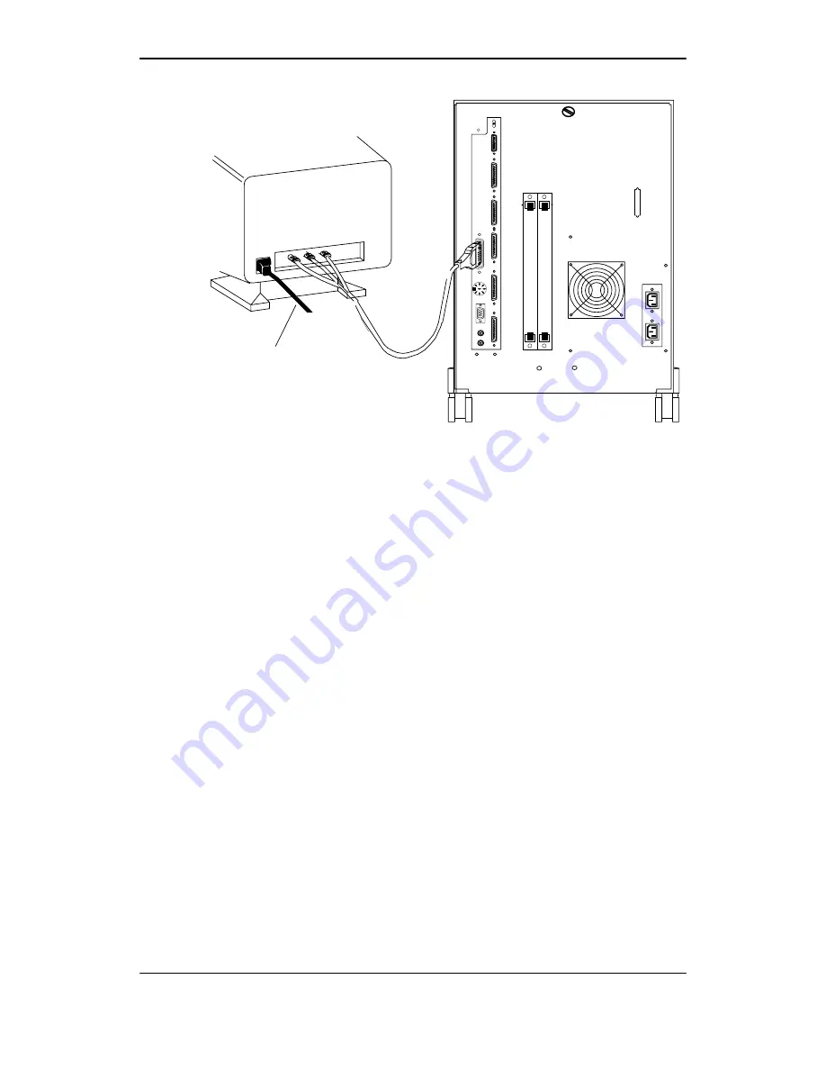
Monitor (rear view)
R G B
Computer Unit Rear Panel
Figure 2–3
Connecting the color monitor
IMPORTANT:
Turn the ends of the BNC cables clockwise to lock them in place.
3. Plug the holes in the other end of the monitor cable into the
graphics board connector pins on the back of the computer unit.
Figure 2–3 shows the 8–bit graphics controller (base configuration).
4. Plug the female end of the monitor power cord into the ac connector
at the back of the monitor, as seen in Figure 2–3. Plug the male end
of the monitor power cord into a grounded wall ac outletl.
Summary of Contents for AViiON 550 Series
Page 2: ......
Page 6: ......
Page 12: ...Joining our users group x 014 002250 01 ...
Page 86: ...Opening and closing the computer unit 4 12 014 002250 01 ...
Page 96: ...Installing a drive assembly 5 10 014 002250 01 ...
Page 188: ......
Page 191: ......


