Planning a SCSI bus configuration
3-8
014–002250–01
"
The following steps outline how to prepare a SCSI drive for
installation.
IMPORTANT:
For device-specific information about setting the SCSI
jumpers/switches and removing the terminator resistors, refer to
the list of drive installation manuals in the Guide to AViiON
and
DG/UX
System Documentation.
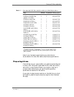
1. Set SCSI ID jumpers according to your SCSI bus plan. Refer to your
drive documentation for instructions.
IMPORTANT: Each SCSI drive or SCSI adapter board located in a
storage subsystem must have its own unique
SCSI ID number.
2. Make certain the drive’s jumper and/or switch settings comply with
the following operating parameters:
D
Set all disk drives for sequential drive motor start. With this
feature enabled, the drive delays starting up its spindle motor a
number of seconds (a multiple of the SCSI ID number) when
you power up your system.
D
Set all drives so that the SCSI bus (host system) provides
terminator power rather than the drives themselves. Some
devices specify this option as “SCSI pin 26 ON,” or “power from
interface cable pin 26.”
D
Set any drive that offers these options to enable parity checking
and arbitration.
D
Make sure the bus termination is correct on the new drive:
In an AViiON 5500 or 550 series computer or storage
subsystem, all drives and SCSI adapter boards must have their
SCSI bus terminator resistors removed.
Most stand–alone drives employ an external terminator plug to
terminate the SCSI bus; if your drive does not have an external
terminator, and it will be physically positioned as the last drive
on the SCSI bus, you must install bus termination resistors.
3. Install each internal drive according to the instructions in
Chapter 5 of this manual.
4. Install each external drive according to instructions in the storage
subsystem manual.
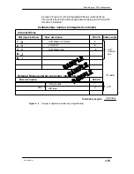
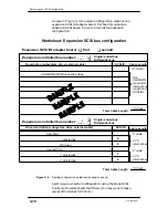
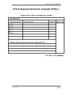
5. Modify or attach the label that identifies the SCSI ID numbers
assigned to the drive(s) to indicate each drive’s location in the unit
and device name. Document your configuration in the worksheets
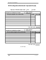
provided at the end of this chapter. (Figures 3–5 and 3–6 provide
samples.)
Summary of Contents for AViiON 550 Series
Page 2: ......
Page 6: ......
Page 12: ...Joining our users group x 014 002250 01 ...
Page 86: ...Opening and closing the computer unit 4 12 014 002250 01 ...
Page 96: ...Installing a drive assembly 5 10 014 002250 01 ...
Page 188: ......
Page 191: ......

