Installing a drive assembly
5-9
014–002250–01
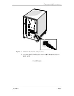
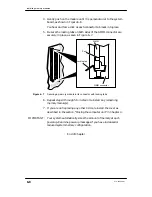
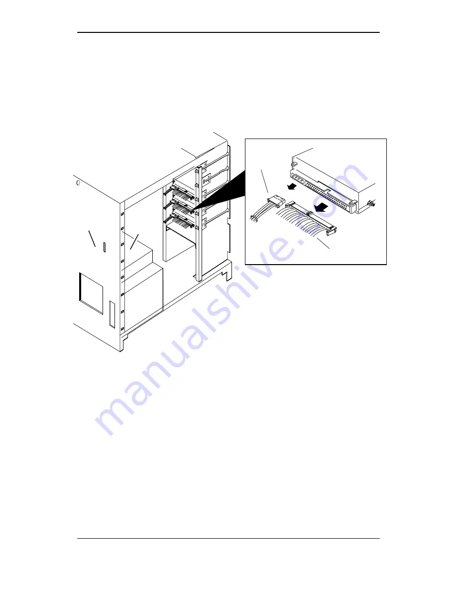
5. Plug a drive power cable and SCSI bus cable connector firmly into
the power and SCSI bus connectors on the drive, as seen in
Figure 5–11. For information on the drive connector locations, refer
to the manual for installing the drive.
IMPORTANT:
You can plug the cables in only one way: the connector on the power
cable has beveled edges to match the power connector on the drive;
the connector on the SCSI cable is keyed.
Drive
SCSI cable
Power cable
Rear panel
SCSI connector
Power
supply
Figure 5–11 Installing the SCSI bus ribbon cable and drive power cable
6. You should now remove the ESD wrist strap, reinstall the cover,
and plug in the computer unit’s power cord as described in the
“Closing the Computer Unit” section of Chapter 4.
After you have closed the computer unit, power up any peripheral
housing units and other peripherals, and then the computer,
according to the instructions in the hardware operating manual.
Then, test your computer system as described in the Using
AViiON
Diagnostics and the AV/Alert
sm
Diagnostic Support
System manual.
End of Chapter
Summary of Contents for AViiON 550 Series
Page 2: ......
Page 6: ......
Page 12: ...Joining our users group x 014 002250 01 ...
Page 86: ...Opening and closing the computer unit 4 12 014 002250 01 ...
Page 96: ...Installing a drive assembly 5 10 014 002250 01 ...
Page 188: ......
Page 191: ......

