Installing the power supply
10-8
014–002250–01
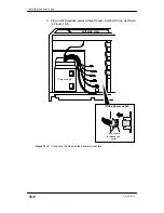
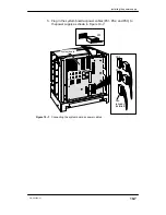
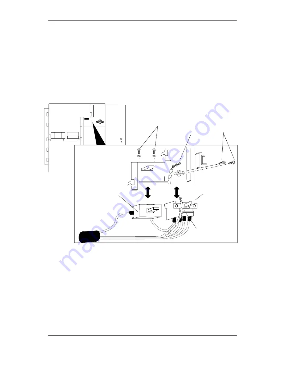
6. Install the front panel power switch assembly as follows (see in
Figure 10–8):
a. Insert the front panel switch into its front panel cutouts.
b. Secure the power switch by inserting two screws from the front
of the computer unit and securing the screws inside the
computer chassis.
c. Install the safety switch by inserting two screws from the top
of the metal chassis and securing them.
d. Attach the ground wire.
Power supply
safety switch
Power
switch
Ground
cable
Secure ground
cable
Install
screws
Install
screws
Figure 10–8 Connecting the front panel power switch assembly
7. Reinstall the side cover as described in the section, “Opening and
closing the computer unit” in Chapter 4.
After closing the computer unit, power up any storage subsystems,
peripheral housing units, and other peripherals. Then start the
computer unit according to the instructions in your hardware
operator’s manual and operating system software documentation.
Next, you should test your computer system as described in the
Using AViiON
Diagnostics manual.
End of Chapter
Summary of Contents for AViiON 550 Series
Page 2: ......
Page 6: ......
Page 12: ...Joining our users group x 014 002250 01 ...
Page 86: ...Opening and closing the computer unit 4 12 014 002250 01 ...
Page 96: ...Installing a drive assembly 5 10 014 002250 01 ...
Page 188: ......
Page 191: ......

