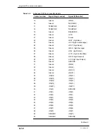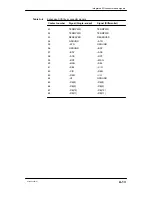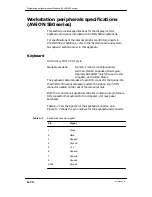
Integrated I/O connectors and signals
A-5
014–002250–01
Asynchronous serial port connectors
Your system console, AV/Alert modem, Uninterruptible Power
Supply (UPS) and other asynchronous serial devices connect to the
Input /Output Controller(s) (IOC) through RS–232–C, 25–pin
female DB25 connectors. These Data Communications Equipment
(DCE) connectors are located at the rear of the computer unit.
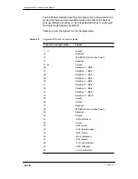
Table A–1 specifies the signals for each pin in these connectors.
Table A–1
Asynchronous port signals
Pin
Signal
Direction
1
Chassis Ground (CG)
n/a
2
Transmit Data (TxD)
Out
3
Receive Data (RCD)
In
4
Request to Send (RTS)
Out
5
Clear to Send (CTS)
In
6
Data Set Ready (DSR)
In
7
Signal Ground (SG)
Both
9–19
Not used
n/a
8
Data Carrier Detect (DCD) *
Out
20 **
Data Terminal Ready (DTR)
Out
22 **
Ring Indicator (RI)
In
23–25
Not used
n/a
*
Proper terminal operation while running the DG/UX operating system requires the
DCD signal pulled up (enabled) by the presence of an IOC board jumper. By default,
DCD is not enabled to the
SERVICE
or
RS232 B
connectors
.
** not used by
OP CON
or
RS232 A
connectors
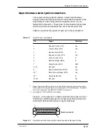
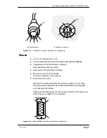
Figure A–1 illustrates pin numbers and shows the signal routing in
the DB25–to–DB25 cables used to connect asynchronous devices to
the AViiON 5500 and 550 series computer bulkhead.
14
13
1
25
female connector
Figure A–1
Asynchronous serial connector pin numbering and cable signal routing
Summary of Contents for AViiON 550 Series
Page 2: ......
Page 6: ......
Page 12: ...Joining our users group x 014 002250 01 ...
Page 86: ...Opening and closing the computer unit 4 12 014 002250 01 ...
Page 96: ...Installing a drive assembly 5 10 014 002250 01 ...
Page 188: ......
Page 191: ......

