Programmers
Replacing a Programmer
PSV5000 Owner’s Manual
- 123 -
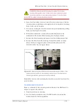
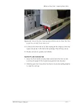
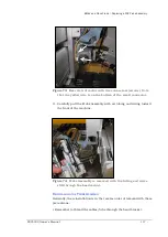
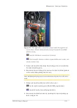
Figure 75:
The right side connection panel inside the right front
access door. Power cables (black arrow), Pneumatic manifold
(white arrow),
and the Ethernet connections (circled).
For LumenX, there is another separate Ethernet router, not
shown in this view.
5.
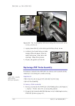
Follow and mark the thin shiny black tubing to the air manifold on
the right mounting plate.
6.
Disconnect the air tubing at the one-touch connector elbow (push in
on the collar while pulling the tube out).
Note: Manifold port plugs must be installed into all ports that will not be
used.
7.
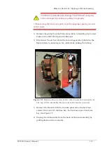
Follow and mark the Ethernet cable to the router :
on the right mounting plate (FlashCORE programmers).
mounted nearby (LumenX programmers).
8.
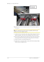
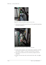
Disconnect the Ethernet cable by pinching the clip and pulling up.
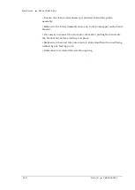
Refer to Figure 76: .
Summary of Contents for PSV5000
Page 12: ......
Page 36: ......
Page 160: ......
Page 161: ...Electrical Schematics for PSV5000 and Equipment ...
Page 162: ......
Page 163: ......
Page 164: ......
Page 165: ......
Page 166: ......
Page 167: ......
Page 168: ......
Page 169: ......
Page 170: ......
Page 171: ......
Page 172: ......
Page 173: ......
Page 174: ......
Page 175: ......
Page 176: ...PROGRAMMABLE MEDIA EXPERTS ...

