■ Setting Up Input and Output Media □ The Tape Output Setup and Operation
PSV5000 Owner’s Manual
- 47 -
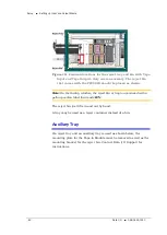
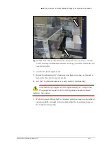
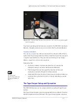
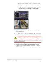
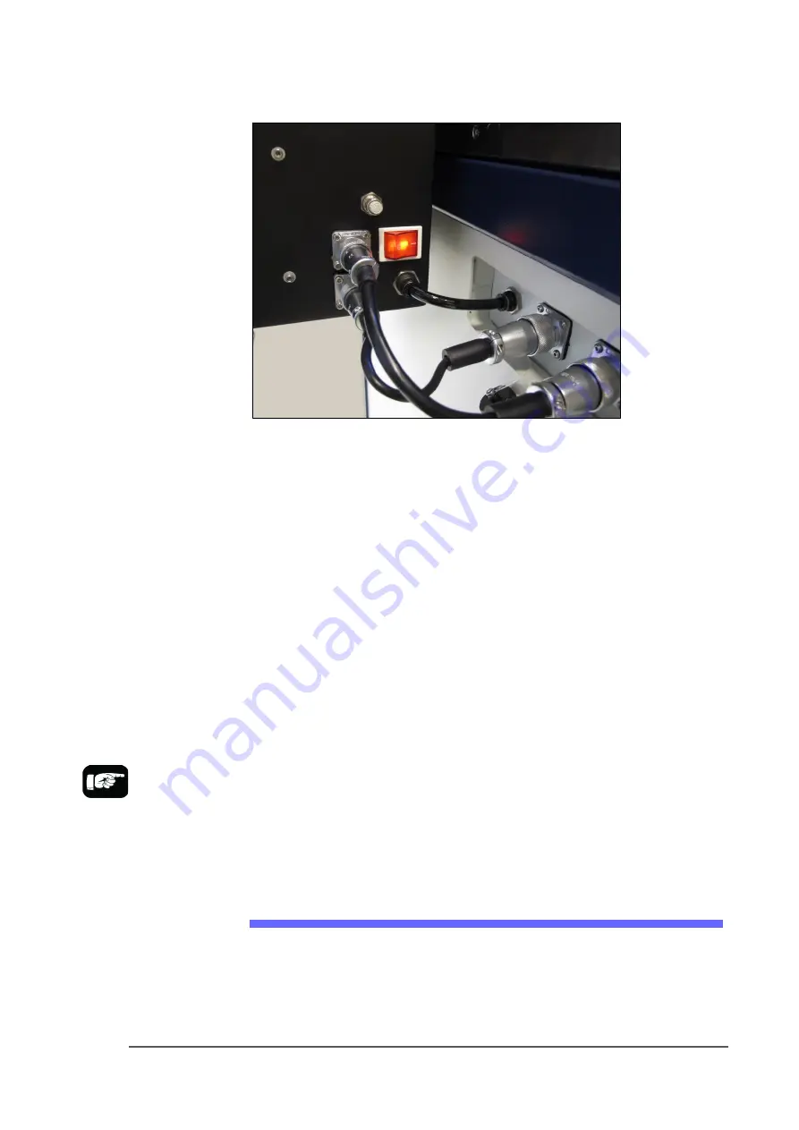
Figure 24:
Connection for the Tray Feeder: air, electrical and signal
(left to right).
Very basic operating instructions are covered in the PSV5000 Operators
Manual. Complete instructions are covered in the Tray Feeder Manual.
T
RAY
A
RRANGEMENTS
You can use a spare tray with an Automatic Tray Feeder (ATF). When a
spare static tray is designated, the devices from that spare tray are used
to replace rejected devices. They are also used during a tray change.
Either a reject tray or bin is also required.
Remember that:
•
the Setup window > Options tab must be set to match the
workspace setup (covered in the Operator’s Manual).
•
The Package File must be taught the location of the reject
container (covered in Chapter 3 of this manual).
•
(Optional) If the Sort-On-Error-Code is used, two Reject Bins are
required. Set up for Sort-On-Error-Code by installing a second
reject bin.
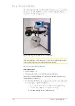
The Tape Output Setup and Operation
The PSV5000 System can be configured with an optional Tape Output
System.
The Tape Output System receives programmed devices directly from the
PSV5000 System via the PNP head. The Tape Output System advances
For more about
Sort-On-Error-Code, see
Monitoring Statistics
on
page 71.
Summary of Contents for PSV5000
Page 12: ......
Page 36: ......
Page 160: ......
Page 161: ...Electrical Schematics for PSV5000 and Equipment ...
Page 162: ......
Page 163: ......
Page 164: ......
Page 165: ......
Page 166: ......
Page 167: ......
Page 168: ......
Page 169: ......
Page 170: ......
Page 171: ......
Page 172: ......
Page 173: ......
Page 174: ......
Page 175: ......
Page 176: ...PROGRAMMABLE MEDIA EXPERTS ...

