■ Setting Up Input and Output Media □ The Tape Output Setup and Operation
PSV5000 Owner’s Manual
- 51 -
5.
Set the taping job parameters at the controller. For more
information see the TM-50 Tape Output System User’s Guide.
6.
Pull the nearest half of the track (table) out to the desired track
width. It stops at detents set to specific tape widths.
7.
Mount the carrier tape reel—
7a.
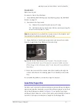
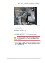
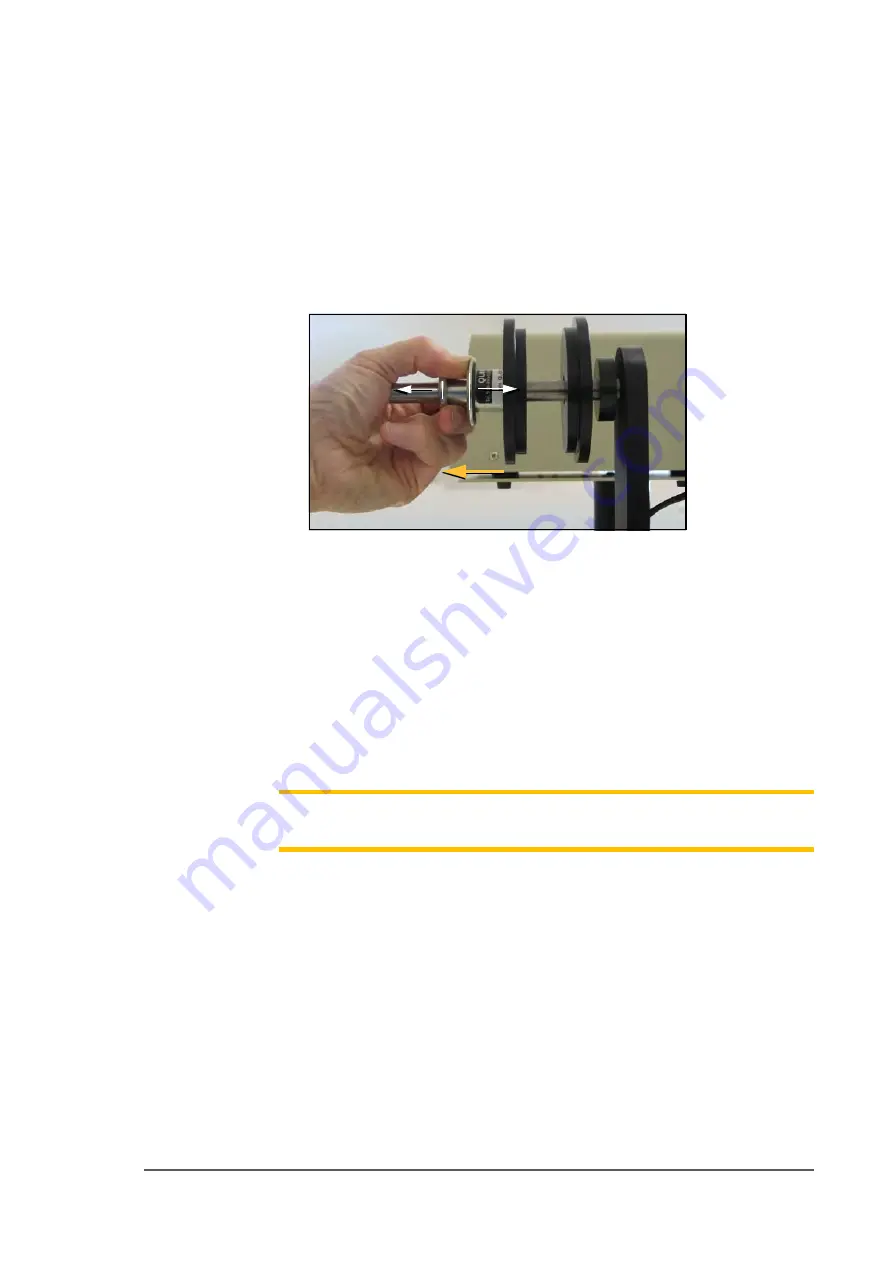
Remove the carrier tape quick lock from the carrier tape
spindle.
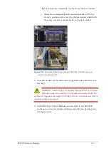
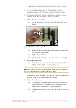
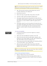
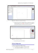
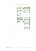
Figure 28:
Removing the spindle.
7b.
Mount the bulk carrier tape reel on the right spindle so the
tape unwinds from the top.
7c.
Replace the quick lock.
7d.
Trim the end of the carrier tape so it is clean and straight.
8.
Route the carrier tape—
8a.
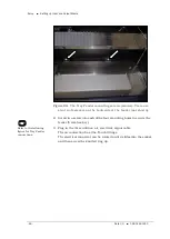
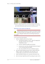
Guide the carrier tape into the loading track. It should feed
right to left through the loading track easily.
Note:
Lowering the feed reel support arm can reduce drag if the angle at
which the carrier enters the loading track is too steep.
8b. Bring the end of the carrier tape past the sealer and engage the
sprocket holes on the teeth of the drive sprocket.
9.
Mount the cover tape—
9a.
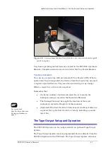
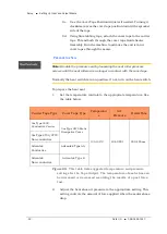
Place a reel of cover tape of the correct width to match the
carrier tape on the cover tape spindle. The tape should
unwind to the right from the bottom of the reel.
9b.
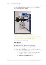
Set the width of the cover tape guide assembly for your size
tape.
Summary of Contents for PSV5000
Page 12: ......
Page 36: ......
Page 160: ......
Page 161: ...Electrical Schematics for PSV5000 and Equipment ...
Page 162: ......
Page 163: ......
Page 164: ......
Page 165: ......
Page 166: ......
Page 167: ......
Page 168: ......
Page 169: ......
Page 170: ......
Page 171: ......
Page 172: ......
Page 173: ......
Page 174: ......
Page 175: ......
Page 176: ...PROGRAMMABLE MEDIA EXPERTS ...

