background image

Administrative Functions  ■    Administrator Functions 

- 68 - 


Data I/O    ■    096-0465-001C 

2e.


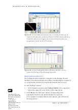
After it finishes, verify that the job passed the tests. 

Note: 

If a programmer does not have a Socket Adapter, or an incorrect 

Socket Adapter is installed, the programmer will automatically be 
disabled. 

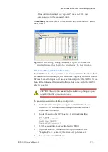
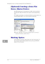
(Optional) Setting TaskLink to Operator Mode


Options to add, remove, and edit Tasks are found in TaskLink’s Task 
Manager Dialog when in Administrator Mode (the default). You can set 
TaskLink to Operator Mode which limits actions to running and viewing 
tasks in the Operator Dialog but not editing or deleting Tasks, Kits, or 
Archived Jobs. 

To switch between Operator Mode and Administrator Mode, see 
TaskLink’s online Help. 

Enhanced Yield Programming


1.


Several selections on the Setup window > Options tab affect yield 
that are not set in TaskLink. Administrators may wish to advise 
operators regarding the setting of the Continuity Retries field and 
the Fail Retries field. 

2.


[Automotive Performance Pak

 only]


Optional: Determine if any of 

the five utilities available with the AP Pak are required for this job. 
They must be set in the CH700 Setup window > Options tab. 

3.


Set security rights for each operator that you do—and do 
not—authorize to make AP Pak changes. Changes to User Rights 
are made in the Security Dialog. 

Note: 

Only installed options are available for selection on the 

Options 

tab. 

If different input media (tape or tray) is desired, the winAH400.ini file may 
need to be edited. See the online Help for instructions editing the 
WinAH400.int file or contact Data I/O support or an authorized technician. 

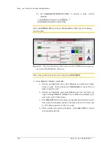
Dry Run (Ignore Programmers) 

(Optional) If you want to do a Dry Run or transfer devices from input 
media to output media with no programming, click 

Ignore Programmers


so it is ON (green); the PNP head will not stop at the programmers. Laser 


For more information 

about Security see 

Creating Security 

Profiles

 on page 65. 


For more information 

on the AP Pak, see the 

CH700 on-screen 

Help. 

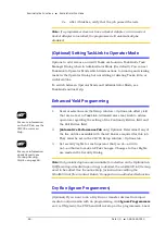
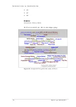
Summary of Contents for PSV5000

Page 1: ... Manual Automated Programming and Handling Snapshot of Features page 10 Specifications page 18 Setting Up Security page 65 Maintenance Schedule Sign Off Chart page 92 and 150 096 0465 001C NOW WITH PROGRAMMERS ...

Page 2: ...r to use in a production environment Data I O does not warrant that the Data I O products will meet your requirements or that operation of the Data I O products will be uninterrupted or error free No part of this document may be reproduced or transmitted in any form or by any means electronic or mechanical for any purpose without written permission from Data I O Corporation with the exception of t...

Page 3: ...R TWO 33 2 Setup 33 Machine Installation 33 Applying Power for the First Time 37 Setting Up Input and Output Media 40 Setting Up the Laser Marking Module 55 CHAPTER THREE 60 3 Administrative Functions 60 Safety Message and Precautions 62 Administrator Functions 63 Maximizing Programming Yields 77 Optional Creating a Data File from a Master Device 80 Marking Option 80 Additional Features 89 CHAPTER...

Page 4: ...andler Computer 129 Troubleshooting 131 Tape Output System Maintenance 140 The Tray Feeder 148 Electrical Equipment Disposal Notice 148 Maintenance Sign off Chart 150 Index 152 Electrical Schematics for PSV5000 and Equipment 157 ...

Page 5: ...rator safe Warnings and Cautions Special paragraphs with red lines are safety warnings as follows WARNING A warning message like this has red text and calls your attention to potentially hazardous situations and practices that might injure people or cause serious monetary loss CAUTION A caution message like this has black text and calls your attention to potentially hazardous situations and practi...

Page 6: ...neral General Hazard Warning Noise Warning may be over 85 db ADVERTENCIA de ruido puede ser más de 85 decibeles Crush Prise Punkt Warnung Eye Hazard Warning ADVERTENCIA de peligro del ojo Auge Hazard Warning Collision Warning ADVERTENCIA de colisión Collision Warning Laser Hazard Warning ADVERTENCIA de peligro del laser Laser Hazard Warning Compressed Air Warning ADVERTENCIA de aire comprimido Dru...

Page 7: ...at are limited to a specific model or piece of optional equipment If the symbol is next to a heading the entire content under that heading is limited to the equipment indicated This Symbol Means Adjacent information is limited to this optional equipment Tape In Module Tape Feeder Only Tape Output Systems Only Auto Tray Feeder Fiber Laser Marking System FlashCORE FC programmers Lumen X LX programme...

Page 8: ...structions in this manual or the Operator s Manual particularly those that describe the system s safety features Safety Systems on page 12 Do not disable or attempt to defeat any of the safety features of this system Serious personal injury and equipment damage can occur if any safety systems are disabled If you suspect that a safety feature of the system is damaged or malfunctioning stop using th...

Page 9: ...ge 27 Always dispose of any other hazardous or residual by products of the production process in accordance with governing laws and regulations Jump Right In Thanks for reading about the safety symbols notes and icons If your PSV5000 System is already set up and you want to skip ahead Be safe see Safety Systems on page 12 Where s the _____ see Machine Components on page 19 How to run a job see the...

Page 10: ...log from the FlashCORE programmer site Error messages if any Device manufacturer and part number if device related Note For later versions of this manual check our website Technical Library Data I O Customer Support The best way to contact technical support is by logging in to our online Support Portal visit www dataio com and click the Technical Support button WORLDWIDE WWW DATAIO COM Data I O Co...

Page 11: ...ies are in lieu of all other warranties expressed implied or arising under law including but not limited to the implied warranties of merchantability and fitness for a particular purpose Repair Service After the warranty period expires Annual Service Agreements are available As the end of your warranty period approaches our sales group will contact you with the Service Agreement options Repairs to...

Page 12: ......

Page 13: ... TQFP CSP TSOP SSOP SON WSON SOIC Device technologies supported include NOR and NAND Flash Micro Controllers Serial EEPROM and the latest e MMC memories The modular design of PSV5000 creates flexibility allowing you to optimize to the level of production required by your facility The PSV5000 System refers to the machine accessories and the software The word Machine is used to mean the physical mac...

Page 14: ...llows Touchscreen monitor which displays real time processes and online Help E Stop button on each side at front left right rear Replaceable programmer modules Software options include a Serial Number Server Built in mounts for optional Tray Feeder and Tape Output Module Clear safety doors front and back Adjustable feet for leveling and wheels for ease of setup and relocation Light tower displays ...

Page 15: ...Word or other word processor 2 Find Language Settings section 3 Add a semicolon to the line for the current language 4 Remove the semicolon from the line for desired language Figure 2 Sample from the winAH400 ini file The language in this sample is set to English 5 Save the file 6 Restart CH700 Software for the changes to take effect ...

Page 16: ...ty doors If your system has a Laser Marking Module it comes with a fume extractor EMERGENCY STOP E STOP BUTTONS Two large red Emergency Stop buttons are located near the top of the PSV5000 System one on either side of the machine When an E Stop button is pressed the gantry stops moving immediately See caution notice below Figure 3 Two Emergency Stop E Stop buttons WARNING Shock hazard Pressing an ...

Page 17: ...of the gantry only It does not remove electrical power from the machine or any optional equipment Turn the main power OFF for safety unless otherwise directed CAUTION Possible product damage Do not use solvents such as acetone lacquer thinner mineral spirits isopropyl alcohol or any type of abrasive compound on the safety doors These products will damage the safety door surfaces and ESD coating an...

Page 18: ...k up a device using the vacuum tools use a squeezable air bladder for suction There are a variety of models sizes and tips Some tips are replaceable Figure 4 A Vacuum Tweezer Data I O PN 565 8000 001 LASER MARKING ONLY FUME EXTRACTOR Used with the Laser Marking option the laser fume extractor removes harmful smoke and hazardous materials from the marking area and safely stores them for proper disp...

Page 19: ...er software CH700 running on the system s Handler Computer direct the PSV5000 System to perform a series of processes including automatic handling programming marking and placement of devices to the output media of your choice The PSV5000 System performs these basic operations when processing devices 1 Pick devices from the input media The pick and place head PNP head unloads devices from the inpu...

Page 20: ...evices into the output media Devices are moved by the PNP head to output media trays tubes or tape Devices that fail one of the programming processes are placed into the reject bin or reject tray Input and Output Options PSV5000 System input and output options are static tray manual tray feeder automatic tube and tape Most combinations of input and output options may be used For example the PSV500...

Page 21: ... System Description Manuals for Optional Equipment PSV5000 Owner s Manual 17 Figure 6 Some of the optional equipment manuals from left to right Laser Marker Automatic Tray Feeder CB Tray Stacker ...

Page 22: ...m 51 inches Width including monitor 1 87 cm 34 inches Height machine doors closed then add light tower 153 cm 62 inches 56 cm 22 in Weight no optional equipment approximate 450 kg 1000 lbs Environment Operating Temperature Hours required for temperature stabilization 13 to 32 C 55 to 90 F 8 hours after transportation Relative Humidity 35 to 90 non condensing Sound level 75 dB or less OTHER Handler...

Page 23: ...ance GANTRY Travels along X and Y axes moving the PNP head to different locations within the work envelope It moves devices in four axes X Y Z and R The PNP head uses different sized probe tips to accommodate the great number of device types that are available See Installing the Correct Probe in the Operator s Manual During operation vacuum at each probe holds a device Vacuum sensors detect whethe...

Page 24: ...sed in many Data I O products and have most algorithm support LumenX programmers are one of the fastest programmer architectures currently available Programmer Modules in the PSV5000 include pneumatic socket actuation Figure 8 Left A FlashCORE Programmer next to the reject bin and Right a LumenX Programmer VISION SYSTEM PSV5000 uses an upward camera for precise picking and placing STATICTRAY MOUNT...

Page 25: ...or cause the system to operate improperly Adding software without specific instruction from Data I O Customer Support will void the warranty and may incur service charges if subsequent service is required KEYBOARD ANDTOUCH SCREEN Both methods of input are available for operation With the touchscreen tap the screen with a finger only not sharp objects such as pens or pencils Note Throughout this Ow...

Page 26: ...ent of AC power and air Optional connections You can connect an Ethernet cable for internet connection CONTROLS Mounted on the Power Panel are the main power switch and the main air regulator and filter There is a second regulator with a separate gauge for adjusting socket opener pressure See Adjusting the Socket Actuator Air Pressure on the Programmers on page 99 Figure 10 Power Panel Facilities ...

Page 27: ...ld never be operated without safety covers in place Observe all warnings regarding laser usage For additional safety information see Laser Safety on page 27 OPTIONAL AUTOMATICTRAY FEEDER Designed to automatically supply trays full of devices to the PSV5000 System the Tray Feeder CB accepts up to twenty thin or thick JEDEC trays Figure 11 The Tray Feeder Optional Tape Input Module The tape input mo...

Page 28: ...oduction Machine Components 24 Data I O 096 0465 001C empty pockets on the carrier tape The carrier tape advances through either a heat seal or pressure seal unit that applies cover tape to the carrier tape ...

Page 29: ...nged unless instructed to do so by Data I O Customer Support Changing parameters can cause failure and or damage to systems or cause improper programming SUPPLIED SOFTWARE The PSV5000 System should never have other software added without consulting with Data I O Customer Support ANTIVIRUS SOFTWARE Customer supplied antivirus software can be installed on the Handler Computer and is recommended CAUT...

Page 30: ...is system TaskLink online Help is available by clicking Help Help Topics It offers procedural steps as well as general information Figure 13 TaskLink online Help It includes update instructions Job Creation Software for LumenX Job Runner and Job Creator are Data I O s latest applications for creating and managing jobs to run on the PSV5000 with LumenX programmers The software resides on the Handle...

Page 31: ...ware on our web site under the SUPPORT tab Then look for PSV5000 under Download the Latest Firmware Figure 14 CH700 Start up window for PSV5000 Laser Software The Laser software is a Windows based application that allows creating parameters required for laser marking jobs as well as initiating laser marking This MarkingMate software is on the Handler computer When the Laser Marking System is set u...

Page 32: ...andard for the Safe Use of Lasers Procedures listed under the Standard include appointment of a Laser Safety Officer operation of the product in an area of limited access by trained personnel servicing of the equipment only by trained and authorized personnel and posting of signs warning of potential hazards WARNING Possible eye and skin injury The laser will fire even when safety doors are open I...

Page 33: ...M 0 424 cubic meters minute of air per occupant This level of ventilation is intended to provide the occupants of the room with sufficient air movement to provide a comfortable environment However because the PSV5000 System generates heat an additional 85 CFM 2 40 meter3 minute is recommended bringing the total room air exchange rate to 100 CFM 2 83 meter3 minute In a room with dimensions of 10 fe...

Page 34: ...recommended minimum envelope size determined by the 1 meter access space required on each side MINIMUM PHYSICAL ENVELOPE Note The numbers below do not include ventilation requirements discussed in the previous heading Ventilation Machine Configuration Width x Depth X axis x Y axis Width x Depth 1 m all sides for access PSV5000 Only 1 5 m x 0 87 m 3 5 m x 2 87m PSV5000 Laser 1 3 m x 0 87 m 3 2 m x ...

Page 35: ... Room Consideration Access Space PSV5000 Owner s Manual 31 Figure 15 Maximum envelope of PSV5000 without optional equipment such as marking Tape In or Tape Output Modules Dimensions in mm Reduced scale ...

Page 36: ......

Page 37: ...r an authorized distributor After the PSV5000 arrives ensure that there is no damage to the exterior of the crate Remove the PSV5000 Machine from the crate and inspect for damage that may have occurred during shipping If no damage is evident unbolt the machine from the shipping pallet For the intended area for PSV5000 installation see Room Considerations on page 29 Leveling When the PSV5000 is at ...

Page 38: ... pressure for all systems within the machine Connecting Air The machine requires clean dry oil free air from an industrial grade compressor PSV5000 Air Requirements Table Note If the compressor cannot maintain the correct air pressure and stable air volume PSV5000 System performance will be affected and may damage devices System Air Volume Air Pressure at inlet regulator on PSV5000 Supply Air Min ...

Page 39: ... is green If air pressure is above or below the acceptable range the readout displays red If it is red out of range contact Data I O Support or a qualified service technician The upper and lower limits cannot be changed without the password Connecting Electrical Power WARNING Electric shock hazard Personal injury could be caused from high leakage electrical current from the main power cable An Ear...

Page 40: ...er to Figure 2 1 Network settings are described in Optional Network Settings on page 38 CAUTION Possible PC virus hazard The PSV5000 System has no antivirus software installed from the factory Prior to connecting to a network Data I O recommends installing antivirus software To install antivirus software refer to Optional Installing Antivirus Software on page 38 ...

Page 41: ... The Socket Adapters required for the job have been installed on all necessary programmer sites See Installing Socket Adapters in the Operator s Manual for more information Note that Socket Adapters can also be installed after power is on Note To tighten socket adapters boards the recommended torque range for FlashCORE programmer screws is 1 4 1 5 Newton Metre Nm 12 4 13 3 pound force inch lbf in ...

Page 42: ...or turned off at the Power Panel Optional Padlock the main air pressure valve so that it cannot be turned back ON while the lock is in place Optional Installing Antivirus Software The PSV5000 System has no antivirus software installed from the factory It is highly recommend that customers install their own antivirus software The software should be set to run virus scans manually rather than at a s...

Page 43: ...he Port numbers are also displayed Port numbers are the same for all programmers on a PSV5000 Machine Addresses and Port numbers can be found as follows 1 Start TaskLink on the target PSV5000 System Closing CH700 will return to TaskLink 2 Click System Options Communication tab The IP Address and site numbers are listed in the lower left corner Figure 17 TaskLink Communication Tab displays IP Addre...

Page 44: ...configuration uses two rows of locating pins and a magnet Specific steps for installing trays are described in the PSV5000 Operator s Manual Note Make sure that the correct devices for the target job are loaded into the input tray and that they have the correct pin 1 orientation If pin 1 orientation doesn t match pin 1 that is set in the Package File it must be corrected Pin 1 on Data I O sockets ...

Page 45: ...et Static Tray Platform 3 mm hex key Figure 18 Static Tray Sensor and bracket Two bracket screws shown at B Only one of the sensor screws is visible arrow This image is for reference only Yours may not be positioned like this 4 Move the sensor into the bottom side of the machine through the sensor cable hole in the working plate Tie it carefully to the cable way To re install the platform reverse ...

Page 46: ...hown Note On the Gantry window the reject bin or tray is associated with a yellow position label that reads RTr The reject bin just lifts in and out by hand A tray may be used as a reject container instead of a bin AuxiliaryTray If a reject tray and an auxiliary tray is used as shown below the mounting plate for the Tape In Module must be removed as well as the mounting bracket for the reject bin ...

Page 47: ...y to Tray with a reject bin trays not shown bottom Two tray mounts must be installed on the left for these configurations Setting Up an AutomaticTray Feeder The PSV5000 System can be configured with an Automatic Tray Feeder The Tray Feeder must be level to the Gantry and square to the PSV5000 Machine For general information about setting it up see the Tray Feeder Owner s Manual that came with your...

Page 48: ...you can run static trays again the file will need to be changed back to ModelTray1 STD INSTALLINGTHETRAY FEEDER The Tray Feeder can only be installed if your PSV5000 was set up for it at the factory or by a Data I O Service Technician REQUIREMENTS Two people to lift it Metric hex key set Key to access door To install the Tray Feeder 1 Shut OFF PSV5000 power See Shutting Down the PSV5000 System on ...

Page 49: ... 5 Rotate the shield up 90 clockwise and fasten in place at the extra hole with the screw removed earlier 6 Get the Tray Feeder fasteners ready and a 5 mm hex key CAUTION Heavy equipment The Tray Feeder weighs 30 kg 66 lb Two people are required to lift it A third person is needed to attach fasteners Use caution 7 With two people lifting the Tray Feeder slide the nose into the shield opening and f...

Page 50: ...ows There are also two fasteners on the back side of the feeder not shown 8 Screw in a screw into each of the four mounting holes to secure the feeder 5 mm hex key 9 Plug in the three utilities air electrical signal cable The air connection has One Touch fittings The electrical connector can be rotated until it slides into the socket and then screw the knurled ring up ...

Page 51: ... a tray change Either a reject tray or bin is also required Remember that the Setup window Options tab must be set to match the workspace setup covered in the Operator s Manual The Package File must be taught the location of the reject container covered in Chapter 3 of this manual Optional If the Sort On Error Code is used two Reject Bins are required Set up for Sort On Error Code by installing a ...

Page 52: ...M 50 Tape Output System User s Guide that came with your Tape Output System INSTALLINGTHETAPEOUTPUT MODULE TOOLS REQUIRED Metric hex key set Three people to lift install the Tape Output Module These steps are for installing the Tape Output Module which can be ordered with the PSV5000 1 On the left side of the machine prepare the small clear safety covers for receiving the Tape Output Module a Loos...

Page 53: ...e Tape Output Module Shield rotates counterclockwise 90 2 Unscrew the five screws that secure large fixed safety shield 4 mm hex key WARNING Possible injury or property damage The Tape Output Module is heavy Use caution Two people are required to lift this equipment Approximate weight 47 63 kg 105 lbs A third person may be required to bolt it into place 3 Install the Tape Output Module onto the pl...

Page 54: ...Guide To set up the Tape Output System 1 Edit the winAH400 ini file for Tape Output 1a Using Windows Explorer locate C CH700 winAH400 ini and make a backup copy for example winAH400backup ini 1b Open the original file with Microsoft Notepad 1c Locate the line TapeOutPutInstalled FALSE and change it to True TapeOutputInstalled TRUE 1d Save the winAH400 ini file and exit Windows Explorer 2 The Tape ...

Page 55: ...from the top 7c Replace the quick lock 7d Trim the end of the carrier tape so it is clean and straight 8 Route the carrier tape 8a Guide the carrier tape into the loading track It should feed right to left through the loading track easily Note Lowering the feed reel support arm can reduce drag if the angle at which the carrier enters the loading track is too steep 8b Bring the end of the carrier t...

Page 56: ...at switch is in on position If not turn on the heat switch To prepare the heat seal 1 Set the temperature controls to the appropriate temperature See the table below Carrier Tape Type Cover Tape Type Temperatur e Air Pressure Dwell Time 3m Type 3000 Conductive Carrier 3m Type 2675 Static Dissipative Cover 135 155 C 40 60 PSI 250 400 ms 3m Type 2701 2703 Non conductive Advantek Conductive Advantek ...

Page 57: ... to move the seal away from the operator Lock the adjuster into place using the position lock knob For Pressure Seal PSA 1 To prepare the pressure seal Set the temperature to Room Temperature 25 2 Advance the tape using Manual Trig button in the LCD 3 Adjust the inner and outer seal roller position Align the roller position over the strip of adhesive on either side of the PSA cover tape Both thumb...

Page 58: ...e point for the first and last devices counted 10 Set the Counter Set the counter STOP value in the LCD to a big number as 9 999 Note Use the counter on the Tape output system if desired However we recommend setting this counter to zero and using the pass quantity on the PSV5000 System to monitor quantity Note When starting a job that uses Tape Output pull the red E Stop On button on the taping ma...

Page 59: ...H700 v2 3 2 to C CH700 to replace exe of v2 3 4 Update below values in the package file 5 134 1500 MSEC LASER SHUTTLE MOVING TIME 6 137 0 NUM INCREASE OR DECREASE LASER POWER OF CUP2 BASED ON CUP1 7 138 0 NUM DISTANCE BETWEEN CUP1 AND CUP2 IN X DIRECTION 8 139 42000 NUM DISTANCE BETWEEN CUP1 AND CUP2 IN Y DIRECTION 5 Start MarkingMate exe 6 Click a blank space on work area and then at the Property...

Page 60: ...same as shown in Figure 32 below They are system values confirm or calibrate initially and each time there is a hardware change Figure 31 The Scale factors in the Lens Setup dialog Laser Software Instruction 1 Copy Template ezm and rename it for your job or start the MarkingMate exe to create a new blank file and then add a text string into the work area for marking ...

Page 61: ...nfirm the real world marking position is set to Cup1 of shuttle Move the red light to cup1 position using the arrow key if they do not match Figure 33 The Preview button 3 Save the file and exit the software CH700 Configuration 1 Make a backup of the winAH400 ini file 2 In the winAH400 ini file make the following changes a Set MarkerSystem UPRHAND to enable the laser ...

Page 62: ...te 3 Click System Gantry Laser tab a Switch on Cup1 Vac then click Preview to confirm red light aims at cup1 If not please run Markingmate to move the red light to match cup1 b Switch on Cup2 Vac and click Preview and set red light for cup2 Change Offset X Offset Y to set distance between cup1 and cup2 in X Y directions c The Power Diff field is the laser energy diference between cup1 and cup2 for...

Page 63: ...etting Up the Laser Marking Module CH700 Configuration PSV5000 Owner s Manual 59 Figure 35 The Laser tab in the Gantry window See instructions in step 3 above for descriptions of controls on the Laser tab ...

Page 64: ...erator functions and Administrator functions Only Administrator functions are covered in this manual Operator functions are covered in the separate PSV5000 Operators Manual although Administrators should be familiar with all operator functions Administrators generally follow the sequence on the next page to create a job ...

Page 65: ...ule CH700 Configuration PSV5000 Owner s Manual 61 Creating a Job Administrator Functions at a Glance Figure 36 Detailed Administrator Functions begin on the next page Shaded boxes are activities that are performed once per package type ...

Page 66: ...amage to equipment this manual uses special symbols paragraphs and color to call your attention to hazardous situations and recommend safe practices to help avoid them Refer to Using This Manual on page 1 in the Preface for symbols and fonts used for safety messages Refer to Safety Systems on page 12 for safety regarding Emergency Stops the safety doors and ESD ...

Page 67: ...page 70 Monitoring Statistics on page 71 Maximizing Programming Yields on page 77 Optional Creating a Data File from a Master Device on page 80 Creating a Laser Marking File if marking on page 81 Automotive Performance Pak on page 89 These functions are discussed in this section Reference List of Operator Functions These functions for operators are discussed in the separate Operators Manual NOTE A...

Page 68: ...s on the Handler computer in the C CH700 folder Creating aTask inTaskLink or Job Creator TaskLink stores Tasks settings for programming job for FlashCORE programmers in a Task database file TSK A Task contains all the information necessary for programming and testing specific devices with a specific algorithm Job Creator stores Jobs for LumenX programmers in directory C LumenX Jobs A Task contains...

Page 69: ...lete instructions on how to create a Task Job in TaskLink see TaskLink s online Help Topics In Job Creator see Job Creator s online Help Topics Both applications will automatically start the CH700 Application Software when Run is clicked OPTIONAL PRESELECTING PROGRAMMERS When CH700 starts programmers that are not used for a particular job can be turned off to improve efficiency see the PSV5000 Ope...

Page 70: ... created TaskLink Task is tested Follow your company s First Article Test Plan The two methods discussed below are 1 Prior to creating a Package file and 2 after creating it TEST PRIORTO CREATING A PACKAGE FILE Outlined below is a suggested test process using Data I O s desktop programmer called FlashPAK III This method allows testing without first having to create the Package File required for PS...

Page 71: ...4a Close Task Manager and change the programming system to PSV5000 System System Select Programming System Re open the Task Manager 4b Select the duplicated job and click Run Note The Package File must be taught if it is new TEST AFTER CREATING A PACKAGE FILE After a Package File is created described in the next few headings or it already exists for this package type and job then this first articl...

Page 72: ...tting of the Continuity Retries field and the Fail Retries field 2 Automotive Performance Pak only Optional Determine if any of the five utilities available with the AP Pak are required for this job They must be set in the CH700 Setup window Options tab 3 Set security rights for each operator that you do and do not authorize to make AP Pak changes Changes to User Rights are made in the Security Di...

Page 73: ...e package and Socket Adapter as well as the number of programmers input and output media and optional equipment such as laser marking if applicable A Package File must be created for each device that uses a different Socket Adapter If a Package File already exists that can be reused same device package same Socket Adapter and same input output media a new one is not necessary PREREQUISITES A Task ...

Page 74: ... a Tray Feeder Teaching tray locations is the same for both ERRORS Please Refer to CH700 on screen Help In the Help table of contents click Browse Sequences Create a Package File Errors Creating the Package File Optimize Movetimes After the equipment locations are taught you can optimize the movement of the PNP head in the work envelope This command Get Movetimes calculates programming times versu...

Page 75: ...cific customer specified processes In addition Data I O offers additional utilities for enhancing yield and reducing errors These include the Automotive Performance Pak see page 89 and several other software packages and hardware such as Factory Integration Software FIS and Serial Number Server SNS TASKLINK SESSION DATA LOGGING For complete instructions on enabling and using TaskLink s Session Dat...

Page 76: ... column Figure 40 At the Package Statistics window statistic can be viewed by Package Type PackageType sts RESETTING PACKAGE STATISTICS The Package statistics displayed correspond to the Package File and therefore to the Socket Adapter used When a Socket Adapter is replaced on a programmer statistics for that Socket Adapter must be reset To reset Package statistics 1 In the Statistics window selec...

Page 77: ... can be used to import and process data output by the CH700 Or use Data I O s Enhanced Statistical Software that comes with the CH700 refer to page 89 CAUTION File corruption hazard Before making any changes to your winAH400 ini file save a backup copy To generate a semicolon delimited output file 1 On the Handler Computer navigate to C CH700 and open winAH400 ini with Microsoft Notepad or IDM Com...

Page 78: ...d with reference vision 04 InspectionYield 05 DevicesInsertedSocket number of devices inserted into socket 06 SocketYield 07 ProgrammerYield 08 ProgSysYield Yield of all programmers together 09 DevicesProcessedMarker 10 MarkingYield 11 SystemThroughputExcWait starts with first device placed excludes wait times 12 SystemTotalThroughputIncWait starts when Run starts includes wait times 13 SystemYiel...

Page 79: ...ToPosID DevicesInspected InspectionPassed InspectionQuality DevicesInserted Socket SocketYield ProgrammerYield ProgSysYield DevicesProcessed Marker DevicesMarked DevicesInputSystem SystemYield SystemThroughputExcWait SystemTotalThroughputIncWait DevicesOutputSystem MachineID ProgTime Inspection quality contains a 4 number record divided by the pipe such as 1 2 3 4 1 100 0 vision pass or XXX X visi...

Page 80: ...tive Functions Administrator Functions 76 Data I O 096 0465 001C 2 dX 3 dY 4 dZ EXAMPLE 100 0 85 0 152 4 1022 4 dX dY are recorded in μm dR is in microdegree μdeg Figure 42 Sample SPC Log File line entry defined ...

Page 81: ...he edges of the devices flashing can cause devices to rest improperly in the sockets Die changes shrinks process improvement for improved wafer yield etc require new algorithms Data I O tracks these changes with vendors and recommends all customers subscribe to the algorithm update program Die processes vary Programming yields can sometimes vary on a normal die Device families recently introduced ...

Page 82: ...ic cleaning adjustment and replacement of worn elements ensure the best possible performance These periodic procedures are outlined in Maintenance Schedule on page 4 2 and should be followed closely Part of regular maintenance is ensuring that the system hardware is in good working order and that settings are accurate To check programmer hardware see FlashCORE Programmer Diagnostics on page 119 Fo...

Page 83: ...tions continuity testing blank checking Measuring yields too infrequently so that a drop in yield rates is not detected until a large number of devices have failed Using the wrong data file selected in TaskLink Job Creator Socket abuse such as digging failed devices out with sharp instruments Changing to a questionable vendor source Lower quality devices tend to produce lower yields ...

Page 84: ...File that can then be used in programming jobs For complete instructions on creating a data file from a master device see TaskLink FlashCORE or Job Creator LumenX online Help Figure 43 TaskLink s online Help includes steps for creating a computer file from a master device Marking Option A Laser Module is an option which marks the surface of the devices It has a separate Operation Manual which came...

Page 85: ...ing uses a laser shuttle except when using Tape Output The shuttle is installed at the factory to transport devices to the laser beam Installing the Laser Shuttle Module TOOLS REQUIRED Metric Hex Key set To install the Laser Shuttle Module 1 On the left side of the machine prepare the small clear safety covers for receiving the Laser Shuttle Module Laser Shuttle ...

Page 86: ...to the storage position and screw it to the fixed safety shield with the screw you just removed Refer to the figure below Figure 46 To install the Laser Shuttle Module rotate the shield counterclockwise 90 2 Unscrew the five screws that secure large fixed safety shield 4 mm hex key 3 Install the Laser Shuttle Module onto the plate in the PSV5000 workspace and screw it down with two screws 5 mm hex...

Page 87: ...derside at approximately the two circled locations near side only shown 4 Connect the air tube to the machine two connectors are shown below 5 Connect the communications cable to the left side of the machine Figure 48 Left the Laser Shuttle air connection circled Right connected Laser safety shield Laser Shuttle Laser Exhaust ...

Page 88: ..._Operation pdf customer letter 983 5075 001A pdf on the Handler PC if your programmer was ordered with the laser option or see the software operation disc for the MarkingMate software the CH700 on screen Help topic Setting up and Teaching Create a Laser Marking File Verifying Proper Laser Operation WARNING Possible health hazard from toxic fumes Laser marking generates vapors fumes and particles t...

Page 89: ...ooting ALIGNING LASER MARKING REQUIREMENTS Two people An image file is in the MarkingMate SW application If the device is not marked check that the laser is aimed at the device correctly 1 Stop any job that is running by clicking Finish on the Run window 2 Turn off the Laser Switch in the Laser power control panel WARNING Serious injury hazard to eyes and skin Do not open or work on the Laser Modu...

Page 90: ...trol panel 3 Open the MarkingMate software window double click the desktop icon 4 Click preview icon in the MarkingMate software Figure 51 The preview icon in the MarkingMate software 5 Another operator open the PSV5000 front left safety door and unscrew the two screws on the inspection door of the Laser Module ...

Page 91: ...n door which is hinged at the buttom to view the laser position red rectangle Figure 53 Inspection door in the open position 7 Use arrow key on the keyboard to move the laser position red rectangle to the desired position lift the door open and recheck Note If the rectangle can t move make sure the laser pattern in the MarkingMate software is selected ...

Page 92: ...55 Save icon in MarkingMate software 9 Install the inspection door to the previous position 10 Turn off the Laser Switch in the Laser power control panel 11 Retry marking device Refer to the previous heading If all appears correct and still there is no mark contact Data I O Customer Support Note The Laser rotor has been leveled at the factory If you experience trouble contact Data I O Customer Sup...

Page 93: ...ntact Data I O Sales Figure 56 The Automotive Performance Pak features appear in the Setup window AUTOMOTIVE PERFORMANCE PAK SOFTWARE DESCRIPTIONS The Automotive Performance Pak AP Pak includes the following software and hardware components ENHANCED STATISTICS The Enhanced SPC Statistical Process Control application is a standard feature on CH700 and allows precise tracking of machine behavior suc...

Page 94: ...part number of the devices LABEL GENERATOR AP PAK OPTION This separate application is a utility for designing labels for reels of device tape or other media Choose size number of fields and layout Call up variables from TaskLink or enter new content Print on demand or automatically after each reel of devices ORDERING AND INSTALLING Ordering the AP Pak involves sending Data I O a number from the Se...

Page 95: ...itional maintenance procedures Note Only individuals trained on these procedures by Data I O or its representatives are qualified to perform maintenance on the PSV5000 System This section describes the preventive maintenance schedule for the PSV5000 System and equipment options with topics appearing in this order Maintenance Schedule starting on the next page Workspace Head and Gantry on page 98 P...

Page 96: ...n page listed Page Items to check Every Day Every day Sockets Clean with dry compressed air Check for wear replace if necessary For HIC Socket Adapters see more information in customer letter Cleaning HIC Sockets PN 983 5053 on our web site Technical Library This link opens the PDF which lists cautions and suggested items such as Cleaning brush PN 5655500901 and ProGold Wipes PN 5705500902 page 98...

Page 97: ...ntry to park before turning OFF Run the Self test by either A turning the PSV5000 System power OFF properly and then ON Shutting Down the PSV5000 System on page 38 or B turning OFF only power to the programmers and then ON with the Programmer Power Switch on the Power Panel If there is a programmer issue a message will display when the next job is run Refer to the Operator s Manual for switch loca...

Page 98: ...ain air filter and replace if necessary Drain fluid page 107 Every month Vacuum Generator filters at PNP head Check vacuum generator filters replace as necessary page 108 Items to check Every Three Months Every Quarter Camera Clean the Camera glass cover page 102 Every Quarter LCD Display Quarterly or as needed Clean the monitor with consumer grade ammonia glass cleaner Spray window cleaner onto a...

Page 99: ...whenever the Filter System alarm sounds and blinks the red lamp Page 126 Items to check Once a Year Every year programmers Run conformance verification test using Data I O s DAB Or have a Data I O Service Technician perform the test Customers with an APS contract have some costs of the test covered in the agreement FlashCORE Programmers DAB part number 910 2200 003 or higher LumenX Programmers DAB...

Page 100: ...ble protective gloves Particle dust mask SAE and metric hex socket wrenches and hex keys Allen Wrenches Data I O hex key set PNs Metric 565 0006 001 and Standard 565 0007 001 Screw driver sets flat and Phillips Metric open end wrenches for the probe tips Shop vacuum cleaner Self Serve Spares Kit page 97 Turning off the Systems When the PSV5000 System will not be used for several days or before per...

Page 101: ...2 0508 001 or higher can be purchased at any time 910 2200 00d or higher Diagnostics Adapter Board DAB only for FC programmer calibration Sales PN FC DIAGNOSTICS BOARD 750 2474 001 or higher an entire probe assembly 480 0070 001 or higher 16 port V LAN Ethernet hub 750 2464 001 or higher programmer power supply 2940220001 or higher Pneumatic Silencer ...

Page 102: ...ation count in yellow until it is exceeded at which time it changes to red SOCKET CLEANING WARNING Vision hazard Pressurized air or debris blown into the eyes or skin could cause bodily damage Always use care and wear protective eye goggles when cleaning with pressurized air 1 Use clean dry compressed air at 6 2 Bars 90 PSI or less to remove dirt from the sockets Open and close the sockets while b...

Page 103: ...s OFF 3 Optional Paddle lock the air shutoff valve ADJUSTINGTHE SOCKET ACTUATOR AIR PRESSURE ONTHE PROGRAMMERS Socket Actuators are built into the FlashCORE programmers on PSV5000 Socket actuation is controlled by air pressure If Socket Actuators are slamming up and down loudly or devices are bouncing the air pressure may be too high If the PNP head does not properly pick or place a device in a so...

Page 104: ...ms persist set the actuator speed refer to the next heading ADJUSTINGTHE SOCKET ACTUATOR SPEED ONTHE PROGRAMMERS THE SOCKET ACTUATOR SPEED WAS SET AT THE FACTORY AND SHOULD NOT NEED ADJUSTMENT If it is determined that adjustment is necessary this procedure requires a Data I O trained technician since it requires having an access door open while the machine power is on REQUIREMENTS Programmer air p...

Page 105: ...row The lower one that the screwdriver is at sets the UP speed FlashCORE programmers shown here 4 Adjust the appropriate flow control 1 2 to 1 revolution clockwise for slower action or counter clockwise for faster action 5 Close the access door and clear the door open warning on the monitor 6 At the Actuate tab of the Gantry window click the Actuate Socket switch to ON while listening and watching...

Page 106: ... areas 2 With air and power OFF remove all devices and materials that may have fallen inside the machine 3 Use dry compressed air to remove all dust and debris from the work surface and from under the machine 4 Dust the safety doors inside and outside with an antistatic cleaner 5 Wipe the top and side panels to remove grease fingerprints and dust 6 Dust the top surfaces of the input output modules...

Page 107: ...cuum switch to ON 2c Open the safety door and place a device on the target probe 2d If the vacuum does not firmly hold the device replace the probe tip with a probe tip of the same size CHECKINGTHE PROBE Check that the probe is not loose Tighten the set screw on the stem if necessary If you suspect or hear an air leak 1 Remove the set screw on the probe stem 2 Pull off the probe stem and check the...

Page 108: ...removing a device from the probe Blow off is produced by a vacuum generator on the PNP head If set too high blow off could cause device misalignment during placement TOOLS REQUIRED Large flat screwdriver Very small flat screwdriver To adjust blow off pressure on any vacuum generator 1 Click System Misc I O 2 At the I O Interface window select the desired vacuum generator probe 1 or probe 2 or both...

Page 109: ... stem which needs to be loosened before adjusting the set screw See the figure below Figure 61 The Blow off adjustment set screw on the vacuum generator is inside a knurled locking stem arrow The vacuum block must NOT be removed as shown here 6 Turn the adjustment screw until the vacuum generator readout displays 1 5 to 2 0 kPa 7 While holding the set screw with the screwdriver tighten the knurled...

Page 110: ...ions installed To view the status of sensors at the main CH700 Setup window click System Misc I O Figure 62 The I O Interface window reports sensor status and allows switching options on or off TO ADJUST PROBEVACUUM GENERATOR SENSORS 1 Finish a job 2 At the Gantry window move the PNP head to the Park position 3 Close the Gantry window and at the System window click Misc I O 4 At the I O Interface ...

Page 111: ...h value and the low value It should be approximately 40 kPa 9 Press the SET button again 10 Check adjustment by blocking and unblocking the probe tip several times and ensuring the green lamp goes on and off each time 11 Repeat these steps for probe 2 12 Turn OFF the vacuum switch for the probe Wipe the probe tip with a clean dry cloth Replacing the Input Air Filter 1 If a job is running Pause or ...

Page 112: ... or replacing vacuum generator parts for vacuum generators on PSV5000 head A clogged or dirty vacuum filter or silencer can cause dropped devices and placement problems at the PNP head REQUIREMENTS metric hex key set flat screwdriver small Phillips screwdriver VACUUM GENERATOR FILTERS 1 Finish a job if one is running 2 Use the Gantry window to move the PNP head to an accessible location such as th...

Page 113: ...d fastener on the underside of the nearest filter housing See the figure below 7 Remove the filter housing and ensure that the O Ring doesn t fall 8 Remove the filter from the housing It should be white or nearly white If dirty or clogged replace with new filter Data I O PN 294 0219 001 See the figure below Figure 65 Removing the PNP head Vacuum Generator filter The yellow arrow points to the wiri...

Page 114: ...acuum generator two 1 5 mm hex key Figure 66 The vacuum generator silencer It is included in the Self Service Spares Kit 5 Inspect the silencer If it looks dirty not white replace it 6 Replace the cover plate Inspecting Gantry Parts CHECKINGTHE PNP HEAD 1 Properly shut OFF the PSV5000 sub systems and machine power Refer to Shutting Down the PSV5000 System on page 38 2 Check that all connectors are...

Page 115: ...r eye protection goggles GANTRY X AXIS LUBRICATION 1 Move the PNP head to the Park position 2 Properly shut OFF the PSV5000 sub systems and machine power See Shutting Down the PSV5000 System on page 38 3 The guard on the back linear guide must slide out to the left or right Therefore remove either the left or right clear workspace side panel Remove the four screws 4 mm hex key and lift the panel o...

Page 116: ...the grease 9 Lubricate the rear ball screw after wiping off the old grease Directly apply new grease to the ball screw sparingly Wipe off any excess 10 Open the front safety doors and remove the four screws securing the front guard of the front linear guide of the gantry 2 mm hex key 11 Remove the screw covering the grease duct 12 Apply grease to the grease duct on each end of the slide block Wipe...

Page 117: ... screw after wiping off the old grease Directly apply new grease to the ball screw sparingly Wipe off any excess 11 Replace all screws guards and shields GANTRY Y AXIS LUBRICATION 1 Open the front and rear safety doors and remove the four screws securing the guard of the Y axis linear guide 2 mm hex key 2 Slide the guard out from either the front or back after pulling slightly to clear the end cap...

Page 118: ...rease to the ball screw sparingly Wipe off any excess 5 Replace all guards and shields Replacing a PNP Probe Assembly Technicians trained on the PSV5000 can remove and re install a Probe Assembly if it is damaged or malfunctioning Requirement Metric hex key set Long set with extended reach is best Spare Probe Assembly To remove a Probe Assembly 1 End a job and move the PNP head to the PARK positio...

Page 119: ... the Correct Probe in the PSV5000 Operator s Manual 4 Disconnect the air hose form the vacuum generator shown in the figure below by pushing on the collar while pulling the tubing Figure 70 Remove the air line at the One Touch air connector at the top of the assembly Remove bracket fasters arrows 5 Remove the bracket with the vacuum generator attached four screws three use 2 5 mm hex key the back ...

Page 120: ...semble by pinching the clip and pulling up Figure 72 Top connector on the P robe Assembly 8 Remove the four fasteners that hold the Probe Assembly to the PNP head Refer to Figure 71 A long 2 5 mm hex key is required 9 Disconnect and remove the Z axis retention spring front side of assembly 10 Remove two wire connectors from the back of the motor See Figure 74 ...

Page 121: ...the small connector 11 Carefully pull the Probe Assembly with air tubing and wiring toward the front of the machine Figure 74 Probe Assembly is removed with the tubing and wires still through the head mount REINSTALLINGTHE PROBE ASSEMBLY Generally the reinstallation is in the reverse order of removal with these precautions Remember to thread the cables tube through the head bracket ...

Page 122: ...ke sure the Probe Assembly mates up to the locating pin on the head bracket It s easiest to connect the two motor wires after putting the head onto the bracket but before screwing it in place Make sure tubes and wires are securely stowed and fixed to avoid being rubbed by any moving parts Remember to re install the retention spring ...

Page 123: ...nge Annual programmer Compliance Verification CV can be performed by Data I O at customer sites This on site visit is included if you have an APS Annual Programmer Support contract customer pays travel costs Optionally customer can purchase a Diagnostic Adaptor Board DAB and perform the compliance diagnostics themselves Contact sales to purchase a DAB Tools required Diagnostic Adapter Board DAB Da...

Page 124: ...ct the antistatic wrist strap to the grounding socket on the front or back of the PSV5000 Machine WARNING Possible collision hazard The high speed and force of the gantry can seriously harm anyone working inside the workspace When working within the machine workspace moving the PNP head must be the responsibility of only one qualified individual All others must stay clear of the machine controls t...

Page 125: ...tic Pass 1 Run Vpp Overcurrent test DUT 1 G1 Vpp overcurrent is sensed at 57 mA DUT 1 G2 Vpp overcurrent is sensed at 57 mA DUT 1 G3 Vpp overcurrent is sensed at 57 mA DUT 1 G4 Vpp overcurrent is sensed at 57 mA DUT 2 G1 Vpp overcurrent is sensed at 57 mA DUT 2 G2 Vpp overcurrent is sensed at 57 mA DUT 2 G3 Vpp overcurrent is sensed at 57 mA DUT 2 G4 Vpp overcurrent is sensed at 57 mA Error DUT 3 ...

Page 126: ...the PSV5000 System by turning OFF the main power switch before working on or near the gantry before opening any access doors or removing any cabinet panels To remove a FlashCORE programmer 1 Properly turn OFF the PSV5000 sub systems and machine power See Shutting Down the PSV5000 System on page 38 2 With the supplied door key open the lower right front access door 3 Locate the target programmer an...

Page 127: ...ew 5 Follow and mark the thin shiny black tubing to the air manifold on the right mounting plate 6 Disconnect the air tubing at the one touch connector elbow push in on the collar while pulling the tube out Note Manifold port plugs must be installed into all ports that will not be used 7 Follow and mark the Ethernet cable to the router on the right mounting plate FlashCORE programmers mounted near...

Page 128: ...enX is similar with screws farther apart 10 Open the front or back safety door to access the workspace 11 Lift up on the target programmer being cautious of the cables that will come out with it Replacement is in the reverse order of removal The Laser Module and Shuttle Laser Marking only Laser Marker System is optional equipment on your PSV5000 Programming System The Laser Module employs a laser ...

Page 129: ... marking dust and other foreign material from the housing 4 Place paper towels cloth and protective gloves into a sealable plastic bag Seal the bag and dispose of as hazardous waste Remove safety goggles WARNING Possible health hazard from toxic materials Government regulations apply to the storage of hazardous waste Ensure that contaminated filters are properly labeled and stored in your hazardou...

Page 130: ...manually turned off WARNING Possible health hazard Lased materials can contain hazardous toxins in the dust that cause eye and skin damage DO NOT use compressed air to remove laser dust or any method that allows the particulate to be released into the work environment Wear safety goggles and disposable protective gloves CLEANINGTHE LASER MODULE AND FUME EXTRACTOR TUBE The filter extraction tube sh...

Page 131: ...5000 UpperHand Fume Extractor Operation Manual To replace the Fume Extractor Filters 1 Properly shut off the PSV5000 sub systems and machine power See Shutting Down the PSV5000 System on page 38 WARNING Possible health hazard Lased materials can contain hazardous toxins in the dust that cause eye and skin damage DO NOT use compressed air to remove laser dust or any method that allows the particula...

Page 132: ...structions and part numbers of the UpperHand pre filter and main filter in the UpperHand Fume Extractor Operation Manual that came with PSV5000 Figure 78 These four steps show filter replacement Refer to the Fume Extractor Operation Manual To finish place the filters and your gloves in the bag and seal the bag and dispose of as hazardous waste Close the access door ...

Page 133: ...ve the air filter 1 Properly shut off the PSV5000 sub systems and machine power See Shutting Down the PSV5000 System on page 38 2 Open the filter door by unscrewing the two knurled knobs The Handler Computer filter door has two knurled knobs white arrows The filter screen slides out Figure 79 The Handler Computer filter door has two knurled knobs white arrows The filter screen slides out 3 Open th...

Page 134: ...Job Creator LX require different CDs than the CH700 updates For more information see the online Help for TaskLink or Job Runner or Job Creator NOTE PSV5000 System algorithms are updated periodically and are available depending on your maintenance plan For more information about update kits or the support agreement plan go to http www dataio com Support Software Firmware Algorithms are updated via ...

Page 135: ... page 133 Programming Problems on page 133 Pick and Place Problems on page 137 Air Pressure Problems on page 138 Tray Feeder Problems on page 139 Handler Computer Failure on page 139 Common Error Messages Lamp Color Error Messages Possible Resolution Red Cannot connect to the motion controller Check that both Emergency Stop buttons are OFF Check that all safety doors are closed Properly shut down ...

Page 136: ...AXIS 2 Conditions A Red ERROR box appears in bottom right corner of the Monitor Contact Data I O Customer Support or a local Data I O approved service representative Red Yellow Error Tape Out If a device is jammed in the Tape Output System clear it Acknowledge the error message by pressing the ESC key Then click OK on the PSV5000 Monitor If above doesn t work call the Service Technician Red Main A...

Page 137: ...ning a job or performing the same steps that led to the trouble 2 Note any dialogs with the Collect Logs button and close CH700 the usual way as follows a Click Finish to stop a job b Exit the Run window c Exit the System window d Exit the Setup window 3 Start Collect PS Logs See heading Starting Collect PS Logs below OTHER PROBLEMS For problems that are NOT programmer related run the Collect PS L...

Page 138: ...uired A log zip file named with the current date and time is saved in the Documents folder C Documents or C Libraries Documents START APP METHOD IN WINDOWS OS The Start App non auto method is the Windows method using the Windows Start menu it offers some options Click Window Start All Programs Data IO Collect PS Logs After starting Collect PS Logs from the Start menu the main window appears where ...

Page 139: ...ption b Type a description into the field available In addition to what you type the description will include the Date and Time the log was captured and the serial number information from the winAH400 ini file 4 Click Collect and ZIP A ZIP file is created and copied to the Windows Clipboard A message advises pasting it into a folder you choose 5 Click OK to the message about pasting the ZIP file t...

Page 140: ...th the Socket Adapter check for bent damaged or worn pins on the sockets If continuity failures persists in the same programmer see Pick and Place Problems on page 137 If a programmer is not performing and you cannot correct the error you can continue to use other programmer sites after disabling the non functional programmer See Disabling Programmers in the PSV5000 Operators Manual or the CH700 o...

Page 141: ...ir pressure refer to Connecting Air on page 34 None A probe attempts to pick a device twice even though it picked up the device the first time The Vacuum sensor may need calibrating See To Adjust Probe Vacuum Generator Sensors on page 106 If programming TQFP 144 you can increase the value for suckup time in the Package File to maximum value of 500 ms See the Setup window System Package File Refer ...

Page 142: ...isplay on the regulator will be green when air pressure is within the correct range and red when it is out of range The regulator has been set at the factory and is not adjustable Red There is no or low vacuum on the PNP probe Check that the probe is not loose and that the O Ring is not destroyed or leaking See Pick and Place Probe on page 103 Determine if the PNP head probe is clogged Clean if ne...

Page 143: ...the trays Probe hits devices in a tray hard at one end and not the other Check that the tray feeder is level Adjust the outside mounting bar if necessary Handler Computer Failure If the Handler computer drive fails its behavior or a message indicates that a computer has crashed Your PSV5000 System is equipped with a mirror backup system called RAID that creates a real time ghost image You will see...

Page 144: ...RAID backup drives In image B the Handler PC cover has been removed this image is a representation only for reference Tape Output System Maintenance The Tape Output System is an optional system for placing and taping programmed devices into device tape Items not covered here can be found in the TM 50 Taping Module User s Guide that came with your PSV5000 System Cleaning the Pressure Seal The Press...

Page 145: ...nd Yes or OK to subsequent dialogs which opens CH700 automatically 5 Click Start 6 Turn on the Tape Output Controller by pushing the red Power button Refer to the figure below 7 At the V TEK start up screen select Setup by pressing the left arrow button Figure 82 Tape Output Module Controller The arrow points to the Power On Off button which is also the Emergency Stop for the Tape Out Module only ...

Page 146: ... pockets to advance to 1 Then press ENT AT THE SPEED MENU set the advance speed between 40 to 100 depending on the device tape width and device size Then press ENT NOTE Prevent device tape breakage and advancement problems with narrower tape widths by setting slower speeds in range 40 to 60 Higher speeds may cause the devices to be dislodged from the pockets or may cause the sprocket holes on the ...

Page 147: ...rime buildup exists on the PSA Seal rollers a Using a shop towel and alcohol or alcohol wipes clean the build up from the cover tape application rollers Hold the alcohol cloth on the roller and rotate the roller 360 b Repeat procedure for the other application roller 11 Inspect the drive sprocket top idler and rubber O Rings for any build up from the cover tape See the figure above 12 If grime bui...

Page 148: ...adjustment screw in clockwise If both tests look acceptable visually inspect the sealed device tape for adhesive that may have been squeezed out during application If adhesive is visible the Seal Roller pressure is too high Decrease the application roller pressure by screwing the PSA Seal pressure adjustment screw out and retest Troubleshooting theTape Output System The Tape Output System contains...

Page 149: ...ance Troubleshooting the Tape Output System PSV5000 Owner s Manual 145 Figure 84 Optical Fiber Amplifiers Cover Tape Present and Empty Pocket respectively Amplifier doors are open in the right side view Front View Right Side View ...

Page 150: ...t amplifier Replace the empty cover tape reel with a full one If the reel still contains cover tape adjust the Cover Tape Sensor Controller See Track Jam Sensor and Controller on page 146 None POCKET EMPTY SENSOR AND AMPLIFIER A Tape Out Unit error message displays and a red LED is illuminated on the Pocket Empty Sensor amplifier Adjust the pocket Empty Sensor See Adjust the Pocket Empty Sensor as...

Page 151: ...ty sensor alerts the operator when a pocket is empty as the device tape approaches the cover taping location ADJUSTTHE POCKET EMPTY SENSOR AS FOLLOWS 1 Set the track width for the target device tape A loosen the two Track Width Lock knobs B pull or push the side nearest the operator to correct width C tighten lock knobs 2 Load a roll of device tape onto the spindle and into the track 3 Loosen the ...

Page 152: ...s for dirt nicks or other signs of damage 4 If the shuttle belts are dirty clean with dry compressed air and wipe with a dry lint free cloth and isopropyl alcohol 5 Check that the shuttle elevator is clean and that trays lay flat Electrical Equipment Disposal Notice For customers in the European Union this symbol displayed on your Data I O product indicates that the item must NOT be discarded with...

Page 153: ...cal Equipment Disposal Notice Cleaning and Inspecting the Tray Feeder PSV5000 Owner s Manual 149 Contact your nearest Data I O office to receive information about returning WEEE labeled products with no charge ...

Page 154: ...eder Maintenance Sign off Chart PSV5000 SN____________ For maintenance instructions see Maintenance Schedule on page 92 Enter name of people responsible or daily check marks Enter initials and date Name Sunday Monday Tuesday Wednesday Thursday Friday Saturday Jan Feb Mar Apr May Jun Jul Aug Sep Oct Nov Dec Jan Feb Mar Apr May Jun Jul Aug Sep Oct Nov Dec Copy this chart to use near your PSV5000 Mac...

Page 155: ...t Nov Dec Monthly Clean inspect Tray Feeder Check input air filter drain fluid Check vacuum generator filters on head Quarterly Check vision Clean safety doors Clean the monitor Replace probe O Ring Semi Annually Check PNP head connections fasteners Clean Handler PC filter Annually Clean and lube Gantry guide rails Perform Programmer Performance Verification test Check vacuum generator silencers o...

Page 156: ...nce Pak 68 Auxiliary Tray 42 B Backup system 139 Blow Off adjusting 104 C Calibration test programmers 119 CH700 description 27 statistics 70 updates 130 Cleaning 92 Collect PS Logs 133 Contact information 6 Continuity retries 68 Cover tape sensor 146 D DAB FlashCORE 97 LumenX 119 Data file 64 Device Jam Sensor Tape Out 144 Device Jam Sensor 146 Devices handling safely 14 marking 84 quality contro...

Page 157: ...t Modules Automatic Tray Feeder 43 auxiliary tray 42 reject bin 41 static trays 40 tape output 47 Install programmers 122 Installation PSV5000 33 room consideration 29 IP Address 38 J Job Folder LumenX 64 Job statistics 71 L Label Generator 90 Language changing 10 Laser filter replacing 127 Laser marking file creating 84 verifying operation 84 Laser Marking Module cleaning 124 Laser Shuttle instal...

Page 158: ...115 PNP Probe re installing 117 replacing 114 Pocket empty sensor 146 Pocket Empty Sensor 144 147 Port Numbers 38 Power applying first time 37 connecting 35 specifications 18 Powering down 38 Programmer air connection 123 diagnostics 119 ehternet connection 123 electrical connection 123 maintenance 93 119 self calibration 93 Programmer support 130 Programmers disabling See the Operator s Manual Pr...

Page 159: ...ving 42 Task creation 64 TaskLink creating a Package file 66 modes 68 session data logging 71 Teaching the Package file 69 Technical support 6 Tool position 13 Transfer devices only 68 Tray Feeder maintenance 148 setup 43 Trays installing See Operator Manaul reject 42 static 40 Troubleshooting air pressure problems 138 common errors 131 Handler PC drive 139 Pick Place problems 137 programming erro...

Page 160: ......

Page 161: ...Electrical Schematics for PSV5000 and Equipment ...

Page 162: ......

Page 163: ......

Page 164: ......

Page 165: ......

Page 166: ......

Page 167: ......

Page 168: ......

Page 169: ......

Page 170: ......

Page 171: ......

Page 172: ......

Page 173: ......

Page 174: ......

Page 175: ......

Page 176: ...PROGRAMMABLE MEDIA EXPERTS ...

Reviews: