background image


PSV7000 Ionizer Kit 

14 | 

P a g e


6.


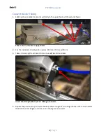
Add/cut approximately 15 cm of air tubing to connect the air regulator to the distributor block. 


Connect air tubing from distributor block to air pressure regulator. 


7.


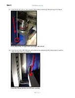
Connect the air tubing from the ionizer to the remaining valve on the air pressure regulator. 


Connect air tubing from ionizer to air pressure regulator. 

From 

ionizer 

Summary of Contents for PSV7000

Page 1: ...2018 Data I O Corporation Part Number 123 4567 001A Data I O PSV7000 Ionizer Kit...

Page 2: ...Chapter 2 Mounting the Hardware 5 Mount the Ionizer 5 Connect the Air Tubing 6 Mount the Air Pressure Regulator 11 Chapter 3 Testing the Ionizer 15 Verify Air and Power 15 Verify ESD Elimination 16 Ch...

Page 3: ...lternately to de ionize the air and optimize ion balance to within 10V in energy saving static electricity elimination mode small holes along the ionizer serve as emitter points for the neutralizing i...

Page 4: ...t remove covers There are no user serviceable parts Tampering with the ionizer and or any of its components may result in damage personal injury electrical shock or fire Never connect Power to any com...

Page 5: ...nizer with mounting brackets B Air hose tubing 3 meters C Air pressure regulator D Electrical wiring Specifications Length 25 329 cm 9 972 in Width 5 890 cm 2 319 in Height w platform 11 227 cm 4 420...

Page 6: ...otential insulation to meet electrical safety standards the electrical components of the system are sufficiently isolated measured to 17 00mA or under with 1 24KVAC for 1 0 sec The majority of PSV7000...

Page 7: ...d routing its cables air electricity Mount the Ionizer 1 Position the ionizer above the left side gantry when facing the front of PSV7000 then use a 3 mm hex key to secure it to the chassis with 2 scr...

Page 8: ...o upper beam 2 Cut the included air tubing into 3 pieces 240 cm 30 cm and 30 cm 3 Take a 30 cm length and insert it into one end side of the ionizer Insert short length 30 cm of air tubing into ionize...

Page 9: ...ir tubing with Y fitting adapter 6 Now take the remaining 240 cm length of air tubing and insert one end into the Y fitting the other end ultimately connects to the air pressure regulator which connec...

Page 10: ...ck of the ionizer Plug in the Power adapter 8 Route the Power and Air cables along the top of the blue chassis and towards the rear of the system and then secure using 4 zip ties looped through each a...

Page 11: ...wn and through the opening in the chassis Route cables down through chassis opening access cut out 10 From the rear of the PSV7000 access the bottom corner opening of the blue chassis to pull the cabl...

Page 12: ...the electrical cable s along the bottom towards ePlate 2 as depicted below Route cables toward ePlate 2 12 Connect the electrical wiring as follows Ionizer connections to ePlate 2 GREEN wire to GND B...

Page 13: ...Utility Panel 1 On the outside of the utility panel prepare the area for drilling Prepare area for drilling 2 Measure the 2 holes depicted below and mark them Measure and mark two holes for drilling N...

Page 14: ...Two holes drilled in Utility Panel 4 On the inside of the PSV7000 use 2 screws PN 220 0025 001 and 2 lock nuts PN 210 0039 001 to mount the regulator the 2 holes in the regulator bracket align with t...

Page 15: ...d air pressure regulator first disconnect the incoming air hose from the distributor block and re route it to the air pressure regulator as depicted below Disconnect incoming air from distributor and...

Page 16: ...nect the air regulator to the distributor block Connect air tubing from distributor block to air pressure regulator 7 Connect the air tubing from the ionizer to the remaining valve on the air pressure...

Page 17: ...verify functionality Verify Air and Power 1 With the air supply ON ensure the air pressure regulator shows a reading between the green markers of 0 10 and 0 14 MPa 15 20 PSI Verify reading on air pres...

Page 18: ...On the front of the ionizer ensure that air is blowing out from each of the nozzles Each nozzle blows air polarized ions Verify ESD Elimination 5 Use an ESD field meter to measure the amount of ESD vo...

Page 19: ...Out Tray Out Tube Out etc Benchmark the default electrostatic field magnitude at test locations Use an ESD field meter to record the Voltage in Volts at each test location WITHOUT the ionizer running...

Page 20: ...t damaged and its emitter points are clear unblocked also check and monitor electrostatic field magnitude with meter to ensure proper operation On a monthly basis check the electrode needle to ensure...

Reviews: