3-4
3.4 OPERATION VOLTAGE SELECTION
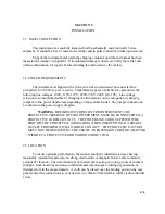
The scanner can be operated at 100, 120, 230 or 240 Volt AC line voltage. The following
explains how to change the voltage settings and the fuse.
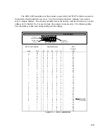
Four possible voltage settings are available as shown on the Power Entry Module cover shows
(IOOV, 12OV, 230V or 24OV). The white pin in one of these holes indicates the present
voltage setting for the scanner. (The 120 Volt AC setting is shown above.) If this setting does
not match the voltage available at your site, then it must be changed before powering on the
scanner. Sites with 220 Volts line power should select 230 V.
Follow the steps below to change a fuse or convert the operating voltage of a scanner.
1. Set the scanner power switch to the OFF position (down).
2. Disconnect the power line cord from the AC wall outlet and from the power cord
receptacle on the power entry module.
3. Inserted a small flat bladed tool into the slot at the left edge of the cover and carefully pry
the cover off the fuse cavity.
4. Grasp the white plastic voltage select board use with a small pair of pliers and pull straight
outward until the voltage select board unseats from the power entry module cover to
change the voltage setting. Hold the board so that you can read the four voltage selection
labels (100, 120, 23O and 240) imprinted on the board. Move the voltage indicator pin to
the opposite side of the board from the desired voltage label. Be sure to seat the pin in the
notch provided on the board's edge. Install the voltage select board so that it is fully seated
in the voltage select cavity (the label side toward the fuse cavity).
5.
Change the fuse if necessary. Carefully replace the power entry module cover making sure
the voltage indicator pin is seated properly in the appropriate hole.
3.5 ADDRESS SELECTION
100 V
120 V
230 V
240 V
Summary of Contents for 160A
Page 8: ...1 4 Blank Page ...
Page 10: ...2 2 Blank Page ...
Page 26: ...4 8 Blank Page ...
Page 30: ...5 4 ...
Page 41: ...6 11 ...
Page 43: ...6 13 ...
Page 47: ...6 17 ...


