3-5
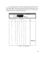
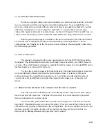
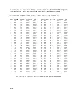
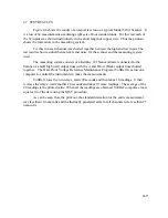
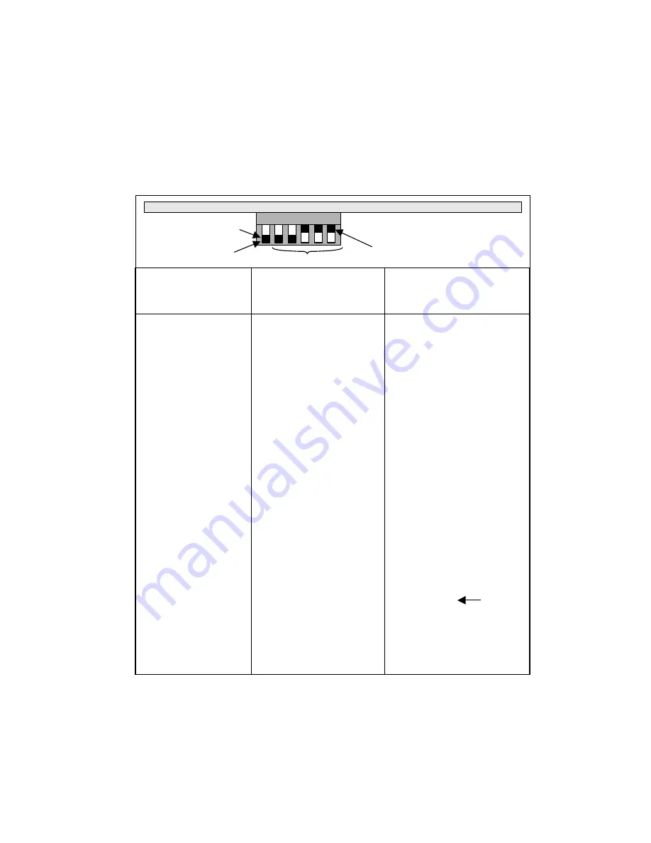
The IEEE-488 bus address of the scanner is selected by the “DIP” switches located on
the interface board under the top cover. The five switches labeled 1 through 5 are used to
select a unique address. The scanner normally leaves the factory with the switches set to a bus
address of 24. Switch No. 6 is used to lock the scanner in remote only. The following table
lists the address codes and corresponding switch settings:
ASCII Code Character
Address Switches
5 Bit
Decimal
Listen
Talk
A5
A4
A3
A2
A1
code
SP
@
0
0
0
0
0
00
!
A
0
0
0
0
1
01
"
B
0
0
0
1
0
02
#
C
0
0
0
1
1
03
$
D
0
0
1
0
0
04
%
E
0
0
1
0
1
05
&
F
0
0
1
1
0
06
`
G
0
0
1
1
1
07
(
H
0
1
0
0
0
08
)
I
0
1
0
0
1
09
*
J
0
1
0
1
0
10
+
K
0
1
0
1
1
11
`
L
0
1
1
0
0
12
−
M
0
1
1
0
1
13
.
N
0
1
1
1
0
14
/
O
0
1
1
1
1
15
0
P
1
0
0
0
0
16
1
Q
1
0
0
0
1
17
2
R
1
0
0
1
0
18
3
S
1
0
0
1
1
19
4
T
1
0
1
0
0
20
5
U
1
0
1
0
1
21
6
V
1
0
1
1
0
22
7
W
1
0
1
1
1
23
8
X
1
1
0
0
0
24
FACTORY
9
Y
1
1
0
0
1
25
SETTING
:
Z
1
1
0
1
0
26
;
{
1
1
0
1
1
27
<
\
1
1
1
0
0
28
=
}
1
1
1
0
1
29
>
~
1
1
1
1
0
30
TABLE 3-1 BUS ADDRESS
6 5 4 3 2 1
Position 1
away from board
Remote Lock
switch
Address 24 shown
Interface Board
Position 0
towards board
Summary of Contents for 160A
Page 8: ...1 4 Blank Page ...
Page 10: ...2 2 Blank Page ...
Page 26: ...4 8 Blank Page ...
Page 30: ...5 4 ...
Page 41: ...6 11 ...
Page 43: ...6 13 ...
Page 47: ...6 17 ...


