4-3
4.3 SCANNER CONFIGURATION
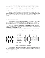
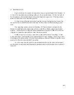
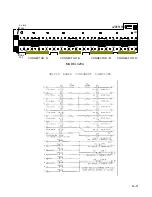
In order to compare voltage reference standards, two units at a time must be connected
in series opposition with the unit negative terminals tied together. To accomplish this, two
relays are connected to each unit with one relay switching to an output line marked A, and the
other relay switching to a second output line marked B. A second contact on each relay
connects the negative terminals to common lines. As shown in Figure 4.3 the A and B lines are
connected to a measuring system to obtain the small difference voltage between the two units.
Both the positive and negative terminal of the unit is switched so that when both relays
are open the unit is completely floating to minimize leakage current problems. The two
common lines are brought out to the rear panel, but are normally shorted together when using
the NBS design procedure.
4.4 LOGIC CIRCUITS
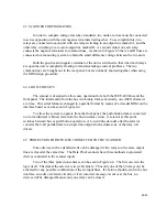
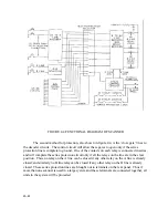
The scanner is designed to allow easy operation from both the IEEE-488 Bus and the
front panel. The information from the bus is in binary form sent serially, one ASCII character
at a time. This serial format is changed to a parallel format by means of a decoder ROM on the
interface board as can be seen in Figure 4.4.
To allow the system to operate from the front panel, the push-button data is converted
to a form identical to binary data from the bus interface circuit. A selector at this point
switches between bus or push-button operation. A 6-to-64 line decoder after the selector
converts the 6-bit parallel data to a single line output which actuates one of the relay coil
drivers.
4.5 PROTECTION FOR DEVICES CONNECTED TO THE SCANNER
Some devices such as standard cells can be damaged if two relays on the same output
line are closed at the same time. The Data Proof scanners have three methods to protected
devices connected to the scanner inputs.
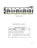
Two of the three protection schemes can be seen in Figure 4.4. The first one is in the
logic itself. The data at the selector is in six bit binary. Thus only one of the 64 relays can be
activated for any possible combination of the six input lines. If a failure should occur in the bus
interface, encoder or selector circuits, or if an incorrect message is sent over the bus, no
devices will be damaged because only one relay can be closed.
Summary of Contents for 160A
Page 8: ...1 4 Blank Page ...
Page 10: ...2 2 Blank Page ...
Page 26: ...4 8 Blank Page ...
Page 30: ...5 4 ...
Page 41: ...6 11 ...
Page 43: ...6 13 ...
Page 47: ...6 17 ...

