1-3
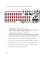
1.3 REAR PANEL CONNECTIONS
SCANNER INPUTS
Opt 1: Two meter (Six foot) cables. Untined solid
copper wire in groups of four pairs.
Opt 2: Low thermal binding posts. Tellurium copper,
gold flashed per MIL-G-45204.
OUTPUT LINES
Four low thermal binding posts
Line A
Line B
Line A common
Line B common
INTERFACE BUS
24 pin IEEE-488 connector, CINCH No. 57-20240
FUSE
0.25 ampere/250 volts time-delay
REFERENCE STANDARD PROTECTION
Screw terminals connected to open collector TTL logic circuit. Terminal
goes low (0 volts) when any relay is closed, and goes high (5 volts through 10
kohm) when all relays are open. This line can be connected in parallel with other
scanners cascaded in a large system to protect standards from being shorted
together. Two systems are provided, one for line A and one for line B.
1.4 REFERENCE STANDARD
PROTECTION SYSTEMS
Three systems are used to help protect standards from being damaged due to
scanner failure or operator error. These systems are described briefly below. See Theory
of Operation Section for complete description.
a. The relays are driven from a decoder so that only one output circuit can be
activated for any possible input combination.
b. Contacts on each relay are connected so that all input lines must be open before
power is available to close a relay.
c. Two push-buttons must be depressed at the same time to actuate any relay.
Requires two hands to operate.
Summary of Contents for 160A
Page 8: ...1 4 Blank Page ...
Page 10: ...2 2 Blank Page ...
Page 26: ...4 8 Blank Page ...
Page 30: ...5 4 ...
Page 41: ...6 11 ...
Page 43: ...6 13 ...
Page 47: ...6 17 ...


