background image

Chapter 4

28

3.

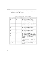
If you are using an external sync input or output, attach the 
horizontal sync input/output to EP332 connector HSYNC and 
the vertical sync input/output to EP332 connector VSYNC.

4.

If you are using an external trigger source, attach the output of 
the external trigger source to EP332 connector TRIGGER.

5.

If you are using an external TTL-level pixel clock, attach the 
output of the clock source to EP332 connector PIX CLK B.

6.

If you are using an asynchronous reset camera, attach the 
expose/reset input of your camera to EP332 connector EXP 
RESET.

Once you have connected all the required signals to the DT3162 
board, apply power to the computer, then apply power to your video 
source.

Using the Camera Interface Module

This section assumes that you have purchased an optional Camera 
Interface Module; the EP321 cable is shipped with the Camera 
Interface Module.

To connect signals to connector J1 on the DT3162 board using the 
Camera Interface Module, perform the following steps:

1.

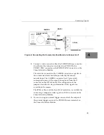
After making sure power to the computer is off, push one end of 
the EP321 cable into the J1 socket at the rear of the DT3162 board, 
push the other end of the EP321 cable into the VCP connector of 
the Camera Interface Module, and tighten the screws on both 
connectors. 

Figure 4

 illustrates this step.

Summary of Contents for DT3162

Page 1: ...DT3162 Getting UM 19133 B Started Manual...

Page 2: ...y implication or otherwise under any patent rights of Data Translation Inc Use duplication or disclosure by the United States Government is subject to restrictions as set forth in subparagraph c 1 ii...

Page 3: ...3 Accessories 4 Getting Started Procedure 5 Chapter 2 Preparing to Use the DT3162 7 Unpacking 9 Checking the System Requirements 10 Installing the Software 11 Viewing the DT3162 Documentation 13 Chap...

Page 4: ...nterface Module 28 Connecting Signals to Connector J2 35 Chapter 5 Verifying Board Operation 37 Overview 39 Using DT Acquire2 40 Chapter 6 Troubleshooting 43 General Checklist 45 Service and Support 5...

Page 5: ...Should Learn from this Manual This manual will help you install and set up your board and required software successfully It is organized as follows Chapter 1 Overview describes the key features of the...

Page 6: ...de information to help you avoid catastrophic damage to yourself or your equipment Items that you select or type are shown in bold Courier font is used to represent source code Related Information Ref...

Page 7: ...om Data Translation describes how to use DT Vision Foundry to create machine vision applications using object oriented image processing tools Where to Get Help Should you run into problems installing...

Page 8: ...About this Manual viii...

Page 9: ...1 1 Overview Key Features 2 Supported Software 3 Accessories 4 Getting Started Procedure 5...

Page 10: ...ock with frequencies ranging from 0 to 40 MHz Accepts an external trigger with selectable polarity Provides programmable brightness settings from 0 to 255 and programmable contrast settings from 0 to...

Page 11: ...isual C in Windows 98 Windows Me Windows 2000 or Windows XP Refer to Chapter 2 starting on page 7 for information on installing the DT3162 software DT Acquire2 This software is provided on the Imaging...

Page 12: ...l video inputs a screw terminal block for attaching external 12 V power and a screw terminal block for attaching an internal trigger EP321 cable A 2 meter integrated cable assembly that is shipped wit...

Page 13: ...agram shows you where you are in the getting started procedure Figure 1 Getting Started Flow Diagram Install the Board and Configure the Device Driver see Chapter 3 starting on page 15 Connect Signals...

Page 14: ...Chapter 1 6...

Page 15: ...7 2 Preparing to Use the DT3162 Unpacking 9 Checking the System Requirements 10 Installing the Software 11 Viewing the DT3162 Documentation 13...

Page 16: ...iver see Chapter 3 starting on page 15 Connect Signals to the Board see Chapter 4 starting on page 23 Prepare to Use the DT3162 Board this chapter Verify Board Operation see Chapter 5 starting on page...

Page 17: ...ce Department at 508 481 3700 x1394 Customer Service will guide you through the appropriate steps for replacing missing or damaged items If you are located outside the USA call your local distributor...

Page 18: ...east one available PCI 32 bit 33 MHz bus master expansion slot At least 128 MB of RAM A DirectX compatible graphics adapter set to 24 bit or 32 bit color At least one CD ROM drive Window 98 Windows Me...

Page 19: ...r computer is less than version 7 0 you are prompted to install the updated DirectX software which is provided on the Imaging OMNI CD 1 Insert the Imaging OMNI CD into your CD ROM drive Note that in m...

Page 20: ...are prompted to choose your destination location 8 Click Next 9 Click Typical which installs the driver ActiveX control examples and manuals Compact which installs only the driver and ActiveX control...

Page 21: ...e Imaging OMNI CD If you install Acrobat Reader 5 0 from this CD ensure that you open Acrobat Reader and accept the license agreement before performing the following procedure 1 Insert the Imaging OMN...

Page 22: ...View Documentation 10 Click User s Manuals 11 Click DT3162 12 View and or print the PDF manual then close Adobe Acrobat 13 Click Main Menu 14 Click View Documentation 15 Click DT Active Frame Grabber...

Page 23: ...15 3 Installing the Board and Configuring the Device Driver Installing the Board 17 Loading and Configuring the Device Driver 21...

Page 24: ...river this chapter Connect Signals to the Board see Chapter 4 starting on page 23 Prepare to Use the DT3162 Board see Chapter 2 starting on page 7 Verify Board Operation see Chapter 5 starting on page...

Page 25: ...m the following procedure to set up the computer 1 Turn off the computer 2 Turn off all peripherals printer modem monitor and so on connected to the computer 3 Remove the cover from your computer Refe...

Page 26: ...an ISA board Note In most PCI systems any PCI slot can be a bus master 2 Remove the cover plate from the selected expansion slot Retain the screw that held it in place you will use it later to install...

Page 27: ...mputer 5 Carefully lower the board into the PCI expansion slot using the card guide to properly align the board in the slot When the bottom of the board contacts the bus connector gently press down on...

Page 28: ...at the rear panel of the system unit using the screw removed from the slot cover 7 Replace the cover and turn on the computer When you are finished with this procedure configure the device driver usi...

Page 29: ...been loaded configure the DT3162 Device Driver through the DT3162 configuration dialog box To access the DT3162 configuration dialog box perform the following steps 1 Open the Control Panel 2 Double...

Page 30: ...d States If this configuration file does not match your video format select the default configuration file to use then click OK The default configuration file for Europe is ccir ccf 9 When you are fin...

Page 31: ...23 4 Connecting Signals Connecting Signals to Connector J1 26 Connecting Signals to Connector J2 35...

Page 32: ...er see Chapter 3 starting on page 15 Connect Signals to the Board this chapter Prepare to Use the DT3162 Board see Chapter 2 starting on page 7 Verify Board Operation see Chapter 5 starting on page 37...

Page 33: ...input and expose reset signals Connector J2 brings out the strobe output and digital I O signals This chapter describes how to connect signals to the board using the J1 and J2 connectors CAUTION Alway...

Page 34: ...ideo input a horizontal and vertical sync input output a TTL pixel clock input and an expose reset output signal two BNC connectors for attaching two additional video inputs a screw terminal block for...

Page 35: ...t at the rear of the DT3162 board as shown in Figure 3 and tighten the screws on the connector Figure 3 Connecting the EP332 Cable Assembly to Connector J1 2 Connect a video source to EP332 connector...

Page 36: ...ctor EXP RESET Once you have connected all the required signals to the DT3162 board apply power to the computer then apply power to your video source Using the Camera Interface Module This section ass...

Page 37: ...turer The CAMERA connector has 12 pins which correspond to many of the signals brought out from the J1 connector on the DT3162 board The configuration of the jumpers described in step 6 determines whi...

Page 38: ...screw driver lift the round metal cover on the Camera Interface Module to expose the camera jumpers as shown in Figure 5 Figure 5 Exposing the Camera Jumpers on the Camera Interface Module W7 W9 W8 R...

Page 39: ...Expose Resetb b To access the HSync signal on pin 6 install jumper W3 by default this jumper is installed or to access the Expose Reset signal on pin 6 install jumper W2 7 VSync or Expose Resetc c To...

Page 40: ...ed the Expose Reset signal is accessible on pin 6 of the CAMERA connector W3 6 If this jumper is installed the default configuration the HSync signal is accessible on pin 6 of the CAMERA connector W4...

Page 41: ...ed If a specified jumper is not installed the corresponding signal is not available to the camera on the pin specified Only one jumper corresponding to a pin can be installed at a time b Misconfigurat...

Page 42: ...n apply power to your video source Note When 12 V power is applied to the Camera Interface Module the LED next to the 12 V connector lights When the Camera Interface Module detects the rising edge of...

Page 43: ...power to the computer is off 2 Push one end of the EP337 cable into the J2 socket at the rear of the DT3162 board then push the other end of the EP337 cable into the STP15 screw terminal panel Figure...

Page 44: ...l from the DT3162 board The dark filled circles in Figure 7 represent holes that you can use to mount the STP15 on a DIN rail To mount the STP15 on a DIN rail you need two DIN rail mount adapters Phoe...

Page 45: ...37 5 Verifying Board Operation Overview 39 Using DT Acquire2 40...

Page 46: ...er see Chapter 3 starting on page 15 Connect Signals to the Board see Chapter 4 starting on page 23 Verify Board Operation this chapter Prepare to Use the DT3162 Board see Chapter 2 starting on page 7...

Page 47: ...you to Acquire either a single image or continuous images Open a previously saved BMP image Save an acquired image in BMP format Load a configuration file Save a configuration file and Perform a digit...

Page 48: ...er to Chapter 4 starting on page 23 for more information 2 From the DT Acquire2 main menu click File then Select Device 3 Select the alias that you gave to the DT3162 board when you configured the dev...

Page 49: ...pplying the values in the LUT to the incoming video 11 To save this configuration click File from the DT Acquire2 main menu click Load Save Configuration File click Save enter the name of the configur...

Page 50: ...Chapter 5 42...

Page 51: ...43 6 Troubleshooting General Checklist 45 Service and Support 50 If Your Board Needs Factory Service 54...

Page 52: ...er see Chapter 3 starting on page 15 Connect Signals to the Board see Chapter 4 starting on page 23 Verify Board Operation see Chapter 5 starting on page 37 Prepare to Use the DT3162 Board see Chapter...

Page 53: ...heck that your system meets the requirements stated on page 10 4 Check that you have installed the software properly using instructions starting on page 11 5 Check that you have installed your hardwar...

Page 54: ...if a PCI device was not designed to share interrupts To resolve this problem select a different interrupt for each PCI slot in the PCI BIOS To do this enter the system BIOS program this is usually don...

Page 55: ...pears to be invalid Wiring is not connected properly Check your wiring and fix any open connections see the instructions in Chapter 4 starting on page 23 Computer does not boot Board is not seated pro...

Page 56: ...flict can also occur if a PCI device was not designed to share interrupts To resolve this problem select a different interrupt for each PCI slot in the PCI BIOS To do this enter the system BIOS progra...

Page 57: ...mation Acquisition operation timed out The capture properties are not set appropriately Refer to the documentation for your camera or image device and set the capture properties to match the requireme...

Page 58: ...t response and are very affordable contact your local sales office for details Refer to the Data Translation Support Policy located at the end of this manual for a list of services included and exclud...

Page 59: ...upport call include the following information Your name include proper spelling Your company or organization include proper spelling A phone number An e mail address where you can be reached The hardw...

Page 60: ...___ graphics adapter _____________________________ data bus _________________________ I have the following boards and applications installed in my system ____________________________ _________________...

Page 61: ...ary of the issue you are experiencing Your contract number if applicable and Your product serial number or purchase date Omitting any of the above information may delay our ability to resolve your iss...

Page 62: ...our nearest distributor are listed in your Data Translation catalog All return shipments to Data Translation must be marked with the correct RMA number to ensure proper processing 2 Using the original...

Page 63: ...CIM 4 connecting signals to connector J1 26 using the Camera Interface Module 28 using the EP332 cable 27 using the EP337 cable 35 using the STP15 35 conventions used vi customer service 54 D DT Visi...

Page 64: ...ayout 36 selecting an expansion slot 18 service and support procedure 50 setting up the computer 17 slot selection 18 software supported 3 STP15 screw terminal panel 4 35 support e mail 53 fax 53 tele...

Reviews: