background image

40 


Appendix 3 

Frequently-Asked Questions 

This section describes problems that you may encounter while using HS-1500T. If you have any 
questions, please refer to related sections and follow all suggested solutions. If problem still exists, 
please contact your distributor or the service center.


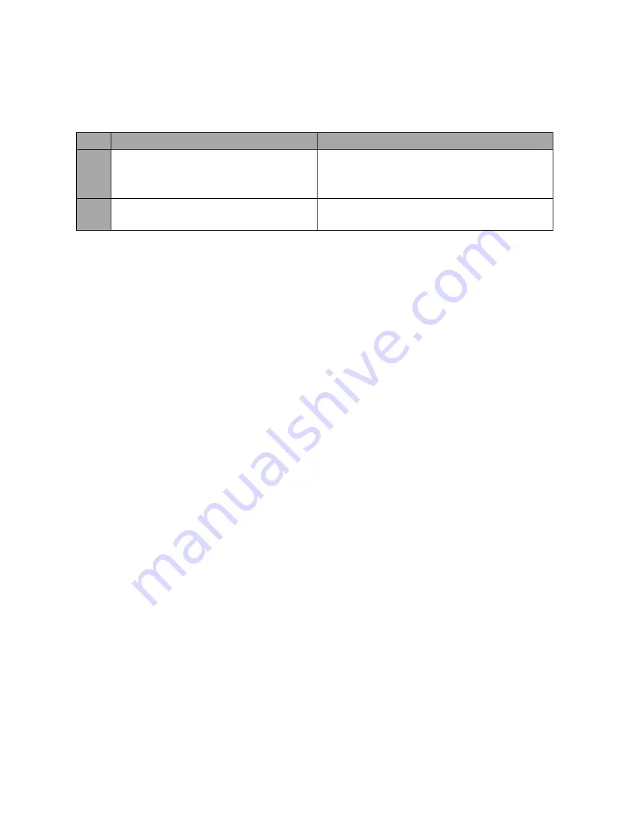
No.  Problems 

Solutions 

1. 

Audio is switched only after the transition 

is complete.  

It is normal that audio is switched after the 

transition is complete regardless of the 

transition method (T-Bar or Auto) used.  

2. 

Jitter is seen on moving images.  

Please make sure the input and output are set 

to the same resolution and frame rate.  


Summary of Contents for HS-1500T

Page 1: ...HS 1500T HD SD 4 CHANNEL HD T PORTABLE VIDEO STUDIO Instruction Manual ...

Page 2: ... 3 1 2 Transition Speed 21 3 1 3 Wipe Effect 22 3 1 4 WIPE Border Size 22 3 1 5 WIPE Border Color 22 3 1 6 BKG Color 22 3 2 PIP SPLIT 22 3 2 1 PIP Source 23 3 2 2 PIP Size PIP Window Size 23 3 2 3 Position X 24 3 2 4 Position Y 24 3 2 5 Split Source 24 3 2 6 Border Size 24 3 2 7 Border Color 24 3 3 PIP CROP 24 3 4 LUMAKEY 25 3 4 1 Lumakey Source 25 3 4 2 Mode 25 3 4 3 Cleanup Level 26 3 4 4 Transp...

Page 3: ...41 APPENDIX 5 DIMENSIONS 44 APPENDIX 6 SPECIFICATIONS 45 SERVICE AND SUPPORT 47 Disclaimer of Product Services The information offered in this instruction manual is intended as a guide only At all times Datavideo Technologies will try to give correct complete and suitable information However Datavideo Technologies cannot exclude that some information in this manual from time to time may not be cor...

Page 4: ...e not sure of the type of power available consult your Datavideo dealer or your local power company 8 Do not allow anything to rest on the power cord Do not locate this unit where the power cord will be walked on rolled over or otherwise stressed 9 If an extension cord must be used with this unit make sure that the total of the ampere ratings on the products plugged into the extension cord do not ...

Page 5: ...r is not covered under warranty Viruses and malware infections on the computer systems are not covered under warranty Any errors that are caused by unauthorized third party software installations which are not required by our computer systems are not covered under warranty All mail or transportation costs including insurance are at the expense of the owner All other claims of any nature are not co...

Page 6: ...onserve natural resources and ensure that it is recycled in a manner that protects human health and the environment For more information about where you can drop off your waste equipment for recycling please contact your local city office your household waste disposal service or the shop where you purchased the product CE Marking is the symbol as shown on the left of this page The letters CE are t...

Page 7: ...equired The HS 1500T also features an audio mixer with balance XLR inputs and unbalance RCA audio inputs more features include PIP WIPE Generator and Tally The HS 1500T has a Joystick that allows the user to Pan Tilt and Zoom the PTC 150T camera In addition the HS 1500T also allows the user to adjust the PTC 150T s Focus IRIS and other settings 1 1 Features Full HD 1080P Video Format Built in HDBa...

Page 8: ...8 1 2 System Diagram ...

Page 9: ...eras via three CAT 6 Ethernet cables The camera videos will be displayed on the respective Multiview quadrants 2 HDMI Video Input The HDMI Video Input port connects an additional video source device and the video will be displayed on the fourth quadrant 3 HDMI Video Output 1 3 Connect to a monitor for Program OUT display or other HDMI destination devices 4 USB F W Upgrade Port USB port for firmwar...

Page 10: ...rce stereo Two Channels of unbalanced MIC input CH L CH R States MIC1 MIC2 MIC 1 L and MIC 2 R are respectively connected to left and right channels MIC1 NC When MIC 1 is connected to the left channel and MIC 2 is not connected to the right channel the right channel switch will replicate MIC 1 signal onto the right channel thus both channels are MIC 1 input signals NC MIC2 When no MIC signal is co...

Page 11: ...button Headphone jack User Memory Audio meter Shift button Headphone volume control knob Transition Effects Camera Presets WIPE transition effect selection Channel Selection Buttons MIX Enable Disable button Preset Buttons WIPE transition effect Enable Disable STR Button PIP Keyer FOCUS IRIS White Balance Enable Disable buttons for PIP Keyer Focus Adjustment Volume Control Program Preview Transiti...

Page 12: ...to browse through the menu and press ENTER button to select an option or MENU button again to exit Reset Button Mode 1 When in Menu Select mode left hand column of the OSD menu pressing the Reset button will reset all current menu items to their factory defaults Mode 2 When in a Sub Menu pressing the Reset button will reset the current menu line only User Memory User Memory buttons 1 3 allow the u...

Page 13: ...ress the AUTO button or move the T Bar WIPE Transition Effect Enable Disable Button Pressing the WIPE button enables the WIPE transition effect after which the WIPE transition effect can be selected To trigger the WIPE transition effect simply press the AUTO button or move the T Bar Wipe Transition Effect Border and Position settings can be found in the OSD menu Start PIP Keyer Enable Disable Butt...

Page 14: ...PIP view on the right To select the Split source i e the program out view please see Section 3 2 5 Transition Control T Bar Manual Transition T Bar is used for manual transition The T Bar can be either all the way up all the way down or anywhere in between When the T Bar is pushed to halfway between the topmost position and the bottommost position the keyboard functions will be disabled PVW and PG...

Page 15: ...Blue Black BLK button Pressing the BLK button places a black screen on the PROGRAM view Preview Source Row Pressing the number buttons along the PREVIEW row selects a video source BKG button Pressing the BKG button will set the Preview OUT to a Matte background which will be displayed on the Program OUT monitor upon the next transition The BKG color can be configured on the OSD MENU and the availa...

Page 16: ... Output The signal strength is determined by the level set with the Master OUT slider The LEDs turn red at 10 dB to indicate clipping distortion Audio Volume dBV 20 10 8 4 0 4 8 10 LED Color G G G G G Y Y R Range dBV 20 12 11 9 5 8 5 6 5 5 5 3 2 1 2 5 5 6 5 8 9 G Green Y Yellow R Red Camera Presets Channel Selection Buttons To control or set up a connected camera first select it by pressing these ...

Page 17: ...ill be in AUTO FOCUS mode IRIS Adjustment To manually control the IRIS setting first press the MANUAL button to enter the manual mode The button LED will be turned ON to indicate that the manual mode is enabled The IRIS dial can then be rotated to set the exposure If the MANUAL button is disabled OFF the camera will be in AUTO IRIS mode White Balance Push Auto Push once to automatically adjust the...

Page 18: ...Make sure the LOCK button is not enabled If the LOCK button LED is ON the joystick is locked press the LOCK button to unlock the joystick LOCK Button When enabled the joystick will be in the lock state To resume its functional status simply press the button once to unlock the joystick Camera MENU Control MENU Button Press once to open the OSD MENU of the connected PTC 150T on the monitor screen Us...

Page 19: ...y generated SMPTE 75 Colour Bars Press again to return to the previously selected video input ZOOM This feature is designed for use with HD SDI and HDMI sources above 720p resolution Press this button to zoom in to the video on the display This is strictly a zooming function and does not alter the native aspect ratio of the source pixels to fill the screen The ZOOM button allows you to toggle the ...

Page 20: ...20 Aspect Ratio Button Sets the Aspect Ratio to 16 9 4 3 Volume Control Adjusts the speaker headphone volume up down MUTE Mutes the audio from the internal speakers or headphone socket ...

Page 21: ...ion WIPE Effect 1 Horizontal 2 Vertical 3 Center 1 WIPE Border Size OFF Small Middle Large Small WIPE Border Color White Yellow Cyan Green Magenta Red Blue Black Red BKG Color White Yellow Cyan Green Magenta Red Blue Black White 3 1 1 Transition Type The HS 1500T provides two types of transition effect which are cross dissolve MIX and WIPE The default setting is MIX 3 1 2 Transition Speed The Tran...

Page 22: ...m size width large is the maximum wipe border width 3 1 5 WIPE Border Color In this option you will be allowed to select a color for your wipe border The available colors are listed as follows White Yellow Cyan Green Magenta Red Blue Black 3 1 6 BKG Color In this option you will be allowed to assign a color to the BKG button The available colors are listed as follows White Yellow Cyan Green Magent...

Page 23: ...to assign the PIP source the available sources are listed as follows Black Input 1 Input 2 Input 3 Input 4 Background Color Bar Tip To quickly assign the PIP source simply press and hold the PIP PGM button and then select a source from the Program BUS 3 2 2 PIP Size PIP Window Size The PIP Size parameter ranges from 1 to 100 with 1 being the smallest and 100 being the largest Therefore 50 would re...

Page 24: ...ram out view on the left and the PIP view on the right The Split source i e the program out view can be selected in this option The available split sources are listed as follows Black Input 1 Input 2 Input 3 Input 4 Background Color Bar 3 2 6 Border Size The Border Size generally allows the user to select an appropriate PIP border width Setting the Border Size to OFF turns the PIP border off Setti...

Page 25: ...eying Note When PIP and Lumakey features are enabled at the same time the lumakey source will be the upper layer and the PIP source will be the lower layer The layer order cannot be changed Option Parameters Parameter Value or Range Default Value Lumakey Lumakey Source Black Input 1 Input 2 Input 3 Input 4 Background Color Bar Input 2 Mode Black White Black Cleanup Level 0 100 20 Transparency 0 64...

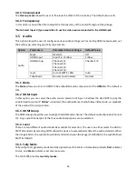
Page 26: ... the HDMI in The default is OFF 3 5 2 HDMI Input In this option you can select the audio source Selection of input 1 4 allows the HS 1500T to play the enabled audio source If Follow is selected the audio will enter Audio follow Video mode i e playback of the audio of the output video 3 5 3 HDMI Group The HDMI Group allows the user to assign the HDMI audio channel The default audio channel is Chann...

Page 27: ...Value or Range Default Value User Mems Load Memory User 1 6 Load Save Memory User 1 6 Save 3 6 1 Load Memory Use the up down arrow to select the desired memory location and load the saved setting by selecting Load Tip The user can also press one of the USER memory shortcut buttons 1 3 on the control panel as a quick way of loading those previously saved User configurations Use the SHIFT button to ...

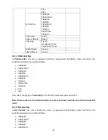
Page 28: ... resolution The available resolutions are listed as follows 1080p 60 1080p 59 94 1080p 50 1080i 60 1080i 59 94 1080i 50 720p 60 720p 59 94 720p 50 576i 480i Once done simply go to Save Setup to confirm the selected output resolution Note Please make sure the output resolution is same as the input resolution to prevent unexpected issues 3 7 2 MV Out Res In MV Out RES the user is allowed to select a...

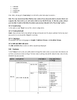
Page 29: ...tart the factory reset process in 2 to 3 seconds after Reset is selected 3 7 5 Language The available OSD menu languages are English Traditional Chinese and Simplified Chinese 3 7 6 MB and KBD Software The MB and KBD software versions will be respectively displayed 3 8 Camera In the Camera menu the user will be able to change the camera name view camera information and perform some basic camera se...

Page 30: ...ters right below are simply information display such as Vendor ID MB Version FPGA Version and Motor Version Video In the Video sub option you will be able to configure the Video Format Mirror Mode Joystick Direction and Joystick Speed The available resolutions in the Video Format parameter are listed as follows 1080i 60 1080i 50 1080p 29 97 1080p 25 720p 59 94 720p 50 1080p 59 94 1080p 50 In Mirro...

Page 31: ...functions Parameters of this sub option are described below Power basically turns ON OFF the selected camera R Gain B Gain The red and blue components can be adjusted ranging from 0 to 255 Tally LED You can either turn the tally light off or enable the red or green tally light ...

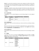
Page 32: ...en setting has been confirmed with the ENTER button it is stored within the switcher s non volatile memory 4 1 MENU Options Main Options Sub Options Parameters Parameters MAIN ADJUST BRIGHTNESS 0 100 CONTRAST 0 100 SHARPNESS 0 100 SATURATION 0 100 TINT 0 100 BACKLIGHT 0 100 NR HIGH MID LOW OFF DLC ENABLE DISABLE VOLUME 0 100 EXIT COLOR 6500 9300 7500 USER COLOR RED 0 100 GREEN 0 100 BLUE 0 100 EXI...

Page 33: ...igure other settings such as Contrast Saturation Sharpness TINT and etc use the Up Down buttons to select the desired option Follow the above procedure to set the new value 4 1 2 COLOR Press ENTER to access the COLOR menu and the first option will be highlighted Press ENTER to select the first color option Use the Up Down buttons to navigate the available color options listed as follows 7500 9300 ...

Page 34: ...ocal dealer or reseller for assistance should they prefer this method This section describes the firmware update process and it should take approximately 15 minutes total time to complete Once started the update process should not be interrupted in any way as this could result in a non responsive unit To update the HS 1500T Monitor you will need The latest firmware update for the HS 1500T Monitor ...

Page 35: ...round is in total black 6 Transparency is set to 64 if an opaque logo is desired Opaque logo can be created by setting the Transparency parameter to 64 Semi transparency effect can be generated by setting the Transparency parameter to a value between 0 and 64 7 Exit the menu after the Logo is properly configured 8 Press the Luma Key PGM button to place the logo on the Program screen or the Luma Ke...

Page 36: ...t REMOTE CONTROL 1 PAN TILT REVERSE P T 2 REMOTE SOURCE DVIP SW 3 SET RS422 4 SET DVIP 5 SET IR 6 PTZ INFO OUTPUT OFF 7 ESCAPE 6 Set the DVIP baud to 115200 SET DVIP 1 DVIP BAUDRATE 115200 2 ESCAPE 7 Connect the PTC 150T to the HS 1500T which should automatically assign an IP to the PTC 150T ...

Page 37: ...ollector output Tally output of input video Program 1 2 No Function 3 Preview 1 Open collector output Tally output of input video Preview 1 4 RCOM GND Ground Ground 5 Program 4 Open collector output Tally output of input video Program 4 6 Program 2 Open collector output Tally output of input video Program 2 7 No Function 8 Preview 2 Open collector output Tally output of input video Preview 2 9 GND...

Page 38: ...PC HS 1500T bin The HS 1500T Keyboard KB Firmware is approximately 27KB and usually with a version number of V1 X HS 1500TM bin The firmware file for the HS 1500T Mainboard MB and OSD MENU fonts is approximately 2 3 MB Example of the firmware display is V1 16 for the mainboard and V1 02 for OSD fonts 2 Connect the USB thumb drive to the F W Upgrade USB port located on the back of the HS 1500T devi...

Page 39: ...te will start approximately 10 seconds after the mainboard finishes booting The startup screen on the monitor disappears and the firmware update will be in progress as the preview row buttons are turned on one at a time from left to right until all buttons are illuminated constant green after approximately SIX minutes At this point the monitor will display a four quadrant Multiview display and thi...

Page 40: ...utions If problem still exists please contact your distributor or the service center No Problems Solutions 1 Audio is switched only after the transition is complete It is normal that audio is switched after the transition is complete regardless of the transition method T Bar or Auto used 2 Jitter is seen on moving images Please make sure the input and output are set to the same resolution and fram...

Page 41: ...not comb or pinstripe cables in the first 20 meters B Use separate patch and equipment cords in the first 20 meters C Avoid use of tie wraps D Use horizontal wire management techniques For example route odd ports to upper management and even ports to lower management E Loosely place cables in vertical wire management F Reduce maximum conduit fill density to 40 G It is recommended to roll the cable...

Page 42: ...side such as the radio interference it is highly recommended to adopt the SFTP to prevent the Ethernet cable from interference SFTP The SFTP Shielded and Foiled Twisted Pair is an Ethernet cable with foil shielding around the individual twisted wires and an overall shield which can be a flexible braid This provides highest protection for the Ethernet cable to prevent it from interference Tips for ...

Page 43: ...et the 23AWG standard and the bandwidth can not meet the 250MHz standard For the CAT7 cable the diameter for most of the flat Ethernet cables can not meet the 22AWG standard and the bandwidth can not meet the 600MHz standard D For many of the multicore Ethernet cables the solid conductor for each core is made by the aluminum wire copper clad aluminum wire or copper clad steel wire rather than the ...

Page 44: ...44 Appendix 5 Dimensions All measurements in millimeters mm ...

Page 45: ...Bottom 70 deg Left 60 deg Right 60 deg Standards PTC 150T Input Resolution 1920 x 1080p 60 50 30 25 1920 x 1080i 60 50 1280 x 720p 60 50 HDMI Input Resolution VGA XGA 1024 x 768 SXGA 1280 x 1024 UXGA 1600 x1200 WUXGA 1920 x 1200 1920 x 1080p 60 59 94 50 1920 x 1080i 60 59 94 50 1280 x 720p 60 59 94 50 480i p 576i p HDMI Output Resolution 1920 x 1080p 60 59 94 50 1920 x 1080i 60 59 94 50 1280 x 720...

Page 46: ...uma Keyer PIP Yes Split Yes Transition WIPE MIX Fade CUT Camera Control Function PAN TILT ZOOM Yes Iris Focus Yes General Operating Temperature 0 C to 40 C 32 F to 104 F Humidity 10 to 80 Voltage DC 48V 190W 48V 4 16A Weight 7 6 Kg ...

Page 47: ...20 2427338 E mail sales datavideo in Tel 91 0120 2427337 A 132 Sec 63 Noida 201307 India India Noida Datavideo India Kochi Tel 91 4844 025336 Fax 91 4844 047696 2nd Floor North Wing Govardhan Building Opp NCC Group Headquaters Chittoor Road Cochin 682035 India Kochi Datavideo Technologies Europe BV Floridadreef 106 3565 AM Utrecht The Netherlands Tel 31 30 261 96 56 Fax 31 30 261 96 57 E mail info...

Reviews: