5-24
Adjustments
Configuring the Magnetic Stripe Module
This option is available only with the Advanced User login.
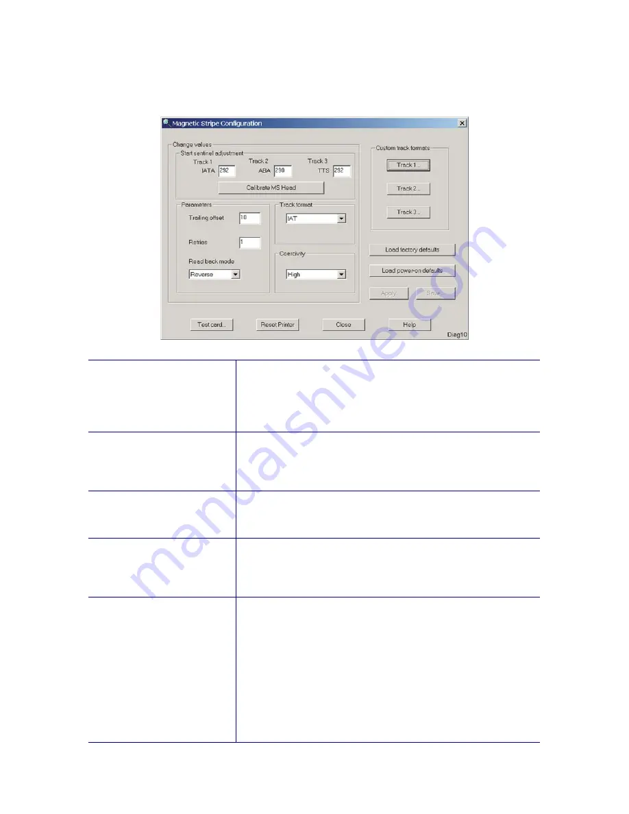
Start sentinel adjustment
The Track # boxes show the current start sentinel values
and the format defined for the track. This allows for
adjusting the start sentinel position to a custom location.
Refer to the Start Sentinel Position adjustment procedure
on page 5-49 for further information.
Calibrate MS head
This option automatically calibrates the printer for
variations in mechanical components. Refer to the Start
Sentinel Position adjustment procedure on page 5-49 for
further information.
Trailing offset
This setting determines how far the card travels to ensure
that trailing clock pulses are encoded for the entire length
of the card.
Retries
This setting indicates how many times the card is re-read in
the event of a read-back error. Note that during a retry,
the card is read in both the forward and reverse direction
regardless of the mode set in read back mode.
Read back mode
This setting determines the direction the card is read
during the initial verification (not including retries).
Forward: This setting provides more reliable data read-
back but decreases throughput because the card needs
to return to the front of the printer before being read. This
setting should be used only if there are frequent read back
errors.
Reverse: (default setting) In reverse mode, the card is read
on its return from the back of the printer. This mode is
faster, but it may result in more frequent read-back errors.
Summary of Contents for CP80
Page 1: ...Datacard CP80 and CP80 Plus Card Printers Service Manual May 2007 Part No 539490 002 Rev C ...
Page 14: ...1 4 Introduction ...
Page 17: ...CP80 and CP80 Plus Service Manual 2 3 Print Engine Functional Block Diagram ...
Page 18: ...2 4 Theory of Operation Laminator Functional Block Diagram ...
Page 22: ...2 8 Theory of Operation LCD Service Mode Menu Diagram ...
Page 52: ...2 38 Theory of Operation ...
Page 158: ...6 6 Removal and Replacement Print Engine Front Wire Routing Diagram ...
Page 159: ...CP80 and CP80 Plus Service Manual 6 7 Print Engine Duplex and Printhead Wire Routing Diagram ...
Page 160: ...6 8 Removal and Replacement Laminator Front Wire Routing Diagram ...
Page 161: ...CP80 and CP80 Plus Service Manual 6 9 Laminator Rear Wire Routing Diagram ...
Page 162: ...6 10 Removal and Replacement Power Supply Wire Routing Diagram ...
Page 163: ...CP80 and CP80 Plus Service Manual 6 11 Print Engine Cable Connection Diagram ...
Page 164: ...6 12 Removal and Replacement Laminator Cable Connection Diagram ...


