CP80 and CP80 Plus Service Manual
6-31
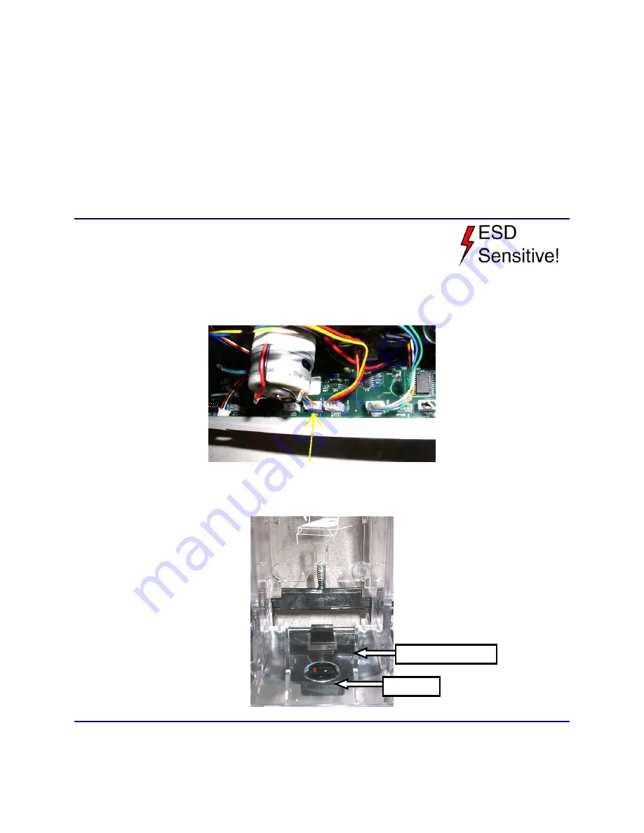
Card Hopper Empty Sensor
The Input Hopper Empty option has a bracket that clips onto the Card Tray. The
sensor fits into the bracket and plugs into the J40 connector labeled
Spare
.
Even though this sensor displays on the Diagnostics Sensor screen, it is used
only by the printer driver API and is not reported to the driver; it will have
no affect on the printer or error messages from the driver. The sensor can be
utilized only after a programmer has done custom development to
incorporate it.
Removal Procedure
1.
Unplug the printer.
2.
Remove the
Main Enclosure
(p. 6-15).
3.
Unplug the Hopper Empty sensor from the J40 connector labeled
Spare
. The
plug is located below the CAM Motor.
4.
Pull the wire free from the printer.
5.
Unclip the sensor bracket from the card input hopper.
Replacement Notes
Use Diagnostics to verify that the sensor is working properly.
Sensor
Sensor Bracket
Summary of Contents for CP80
Page 1: ...Datacard CP80 and CP80 Plus Card Printers Service Manual May 2007 Part No 539490 002 Rev C ...
Page 14: ...1 4 Introduction ...
Page 17: ...CP80 and CP80 Plus Service Manual 2 3 Print Engine Functional Block Diagram ...
Page 18: ...2 4 Theory of Operation Laminator Functional Block Diagram ...
Page 22: ...2 8 Theory of Operation LCD Service Mode Menu Diagram ...
Page 52: ...2 38 Theory of Operation ...
Page 158: ...6 6 Removal and Replacement Print Engine Front Wire Routing Diagram ...
Page 159: ...CP80 and CP80 Plus Service Manual 6 7 Print Engine Duplex and Printhead Wire Routing Diagram ...
Page 160: ...6 8 Removal and Replacement Laminator Front Wire Routing Diagram ...
Page 161: ...CP80 and CP80 Plus Service Manual 6 9 Laminator Rear Wire Routing Diagram ...
Page 162: ...6 10 Removal and Replacement Power Supply Wire Routing Diagram ...
Page 163: ...CP80 and CP80 Plus Service Manual 6 11 Print Engine Cable Connection Diagram ...
Page 164: ...6 12 Removal and Replacement Laminator Cable Connection Diagram ...


