CP80 and CP80 Plus Service Manual
6-121
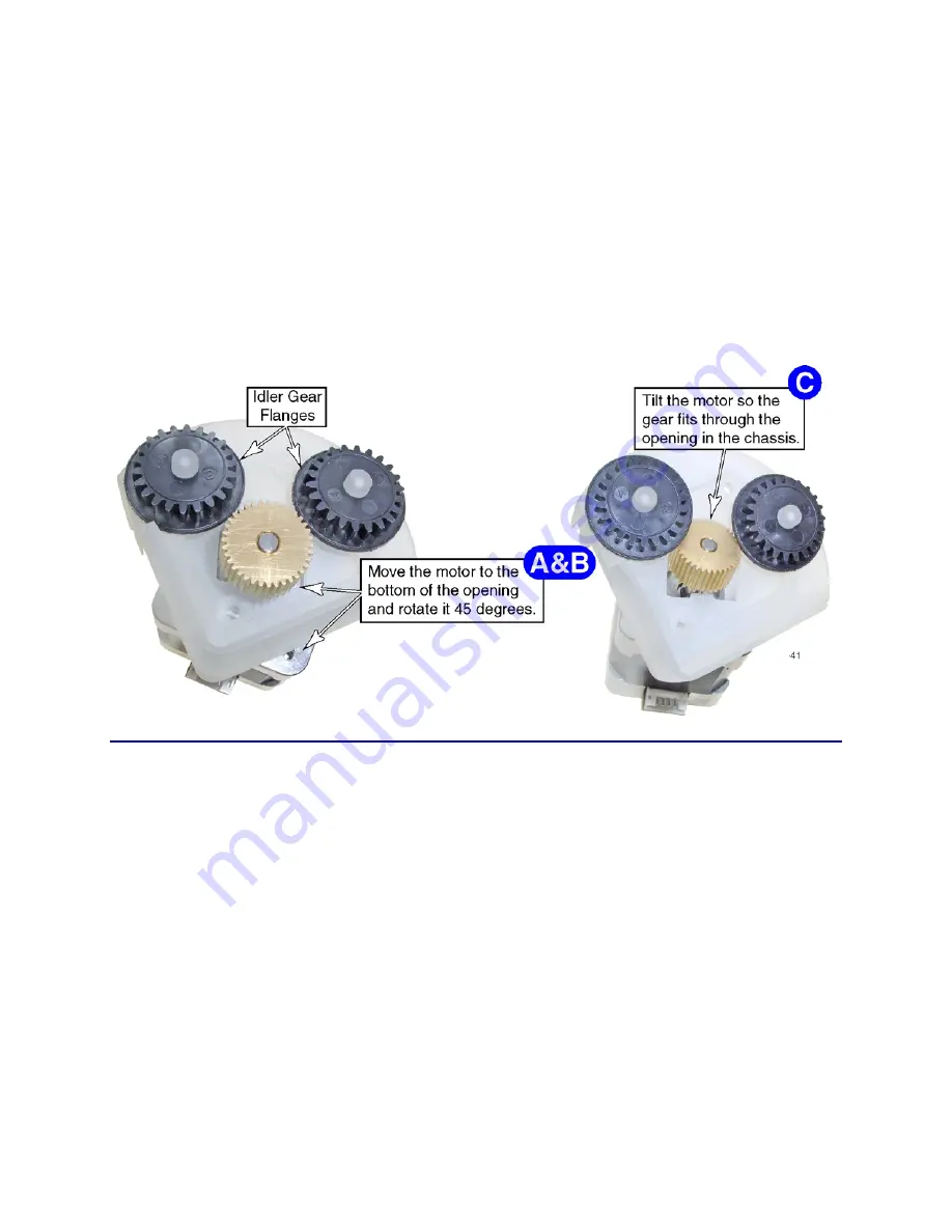
The idler gears have flanges that lock behind the transport roller gears. These
keep the idler gears in place. However, this also prevents the motor from
being removed straight out of the opening.
7.
To remove the motor:
A.
Lower the motor down until the shaft touches the bottom of the cutout in
the chassis.
B.
Rotate the motor 45 degrees so the flat side of the motor is lined up with
the corner of the chassis.
C.
Tilt the motor downward so the top of the drive gear clears the cutout in
the chassis, and remove the motor.
Follow-up Procedure
•
Refer to the
Laminator Cable Connection Diagram
and
Laminator Rear Wire
Routing Diagram
for replacement details.
•
Use the laminator motor tests in Diagnostics to verify the motor is functioning
properly.
•
Print several test cards.
Summary of Contents for CP80
Page 1: ...Datacard CP80 and CP80 Plus Card Printers Service Manual May 2007 Part No 539490 002 Rev C ...
Page 14: ...1 4 Introduction ...
Page 17: ...CP80 and CP80 Plus Service Manual 2 3 Print Engine Functional Block Diagram ...
Page 18: ...2 4 Theory of Operation Laminator Functional Block Diagram ...
Page 22: ...2 8 Theory of Operation LCD Service Mode Menu Diagram ...
Page 52: ...2 38 Theory of Operation ...
Page 158: ...6 6 Removal and Replacement Print Engine Front Wire Routing Diagram ...
Page 159: ...CP80 and CP80 Plus Service Manual 6 7 Print Engine Duplex and Printhead Wire Routing Diagram ...
Page 160: ...6 8 Removal and Replacement Laminator Front Wire Routing Diagram ...
Page 161: ...CP80 and CP80 Plus Service Manual 6 9 Laminator Rear Wire Routing Diagram ...
Page 162: ...6 10 Removal and Replacement Power Supply Wire Routing Diagram ...
Page 163: ...CP80 and CP80 Plus Service Manual 6 11 Print Engine Cable Connection Diagram ...
Page 164: ...6 12 Removal and Replacement Laminator Cable Connection Diagram ...


