2-22
Theory of Operation
Parity Check
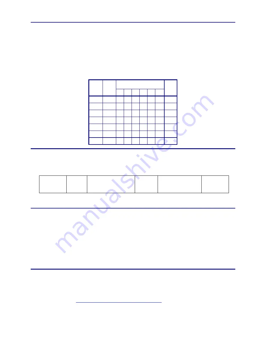
A parity check is a method of determining if an error has occurred. This is
accomplished by adding one extra bit to the end of a binary character code. The
purpose of the parity bit is to make the sum of data bits in a binary word either
even or odd. This way, all words throughout the data string will have the same
parity. In the table below, note that the sum of all the bits in each row is an odd
number. This is called odd parity. With even parity, the sum of the rows would be
an even number.
Binary Char Code
Char Parity
Bit
2
5
2
4
2
3
2
2
2
1
2
0
Bit
Sum
$
0 0 0 0 1 0 0 1
A 1 1 0 0 0 0 1 3
B
1 1 0 0 0 1 0 3
C
0 1 0 0 0 1 1 3
S
1 1 1 0 0 1 1 5
W 0 1 1 0 1 1 1 5
Z
1 1 1 1 0 1 0 5
Data String
Regardless what type of information is written on a magnetic stripe, there is a
basic layout that is followed. This basic layout is shown below.
Leading
Clock
Pulses
Start
Sentinel
Specific Data
End
Sentinel
Longitudinal
Redundancy Check
Trailing
Clock
Pulses
Leading/Trailing Clock Pulses
The actual information written to a magnetic stripe cannot extend fully to the
edges of the stripe. The main reason for this is because the card reader needs to
synchronize its timing to the speed at which the card is swiped through the
reader. Leading and trailing clock pulses permit the reader to gauge the speed of
the card without losing data. (The timing is continuously updated as the whole
card is read, but the leading and trailing clock pulses provide a starting point
without data loss.)
Specific Data
This is the actual data that personalizes the card. This data can represent a
person’s name, birth date, account number, etc. The actual content of this data is
determined by the card issuer or one of the many international standards. (Refer
to the
Magnetic Stripe Primary Data Standards
section for a description of some
common standards.)
Summary of Contents for CP80
Page 1: ...Datacard CP80 and CP80 Plus Card Printers Service Manual May 2007 Part No 539490 002 Rev C ...
Page 14: ...1 4 Introduction ...
Page 17: ...CP80 and CP80 Plus Service Manual 2 3 Print Engine Functional Block Diagram ...
Page 18: ...2 4 Theory of Operation Laminator Functional Block Diagram ...
Page 22: ...2 8 Theory of Operation LCD Service Mode Menu Diagram ...
Page 52: ...2 38 Theory of Operation ...
Page 158: ...6 6 Removal and Replacement Print Engine Front Wire Routing Diagram ...
Page 159: ...CP80 and CP80 Plus Service Manual 6 7 Print Engine Duplex and Printhead Wire Routing Diagram ...
Page 160: ...6 8 Removal and Replacement Laminator Front Wire Routing Diagram ...
Page 161: ...CP80 and CP80 Plus Service Manual 6 9 Laminator Rear Wire Routing Diagram ...
Page 162: ...6 10 Removal and Replacement Power Supply Wire Routing Diagram ...
Page 163: ...CP80 and CP80 Plus Service Manual 6 11 Print Engine Cable Connection Diagram ...
Page 164: ...6 12 Removal and Replacement Laminator Cable Connection Diagram ...


