CP80 and CP80 Plus Service Manual
2-23
Start Sentinel/End Sentinel
The specific data on a card is bracketed by a Start Sentinel and an End Sentinel.
These are used to identify where valid data begins and ends. These two sentinels
are reserved characters and cannot be used for any other reason on the magnetic
stripe. For this reason, the sentinel characters will not be standard letters or
numeric characters. (Just like any other character written to the card, the
sentinel’s binary word also includes a parity bit.)
Longitudinal Redundancy Check (LRC)
This is a final parity check for the entire data string. Unlike the parity bit
mentioned in the preceding section, the LRC is a complete binary word itself,
with the same number of bits as the specific data characters.
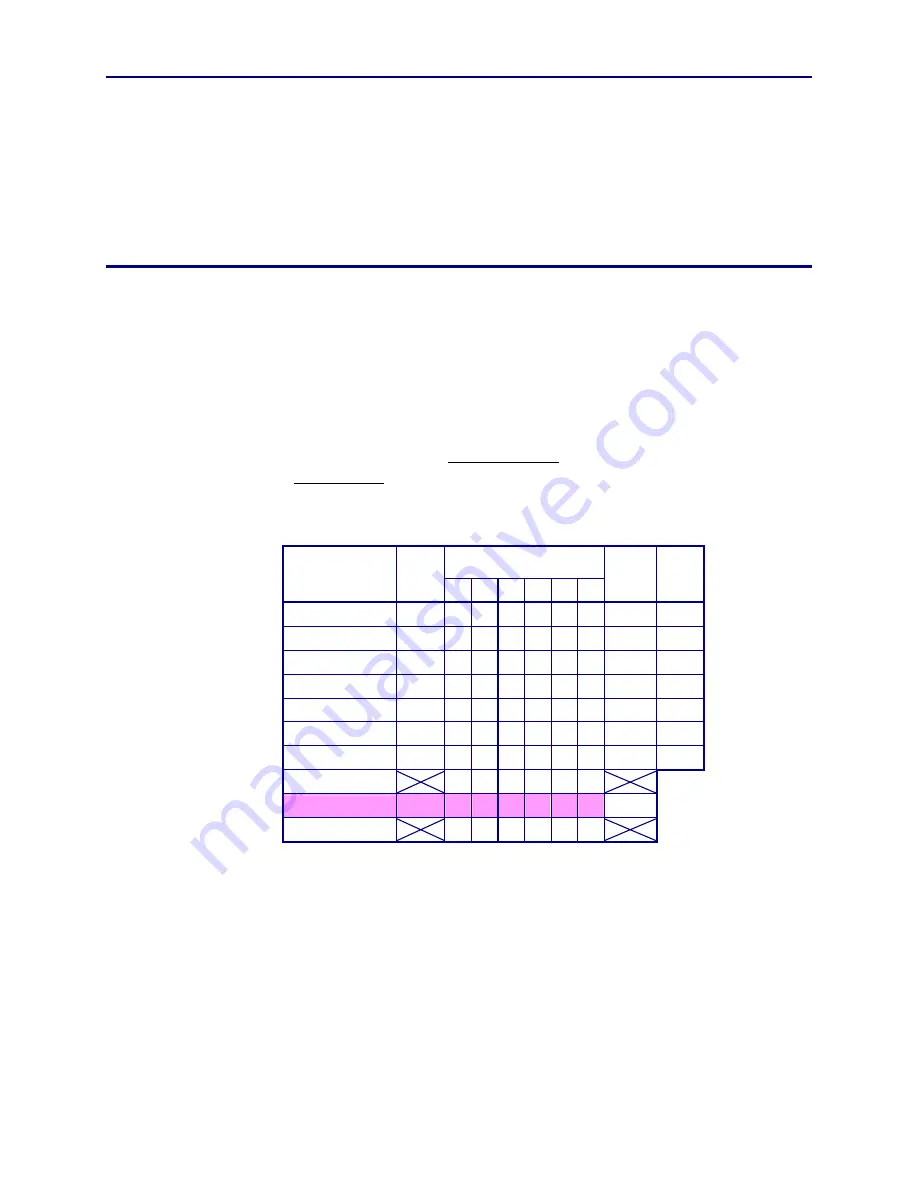
Each bit in the LRC binary word (except its own parity bit) represents a single
parity check for all of the preceding bits in the same position. This can best be
explained by examining the binary data in the tabular form shown below. Each
character’s parity bit makes the horizontal sum of bits an odd number. The LRC
makes the vertical sum of all the individual bits an even number. (The LRC’s
own parity bit sets the parity for the LRC word in the same manner as it would
for any other character.)
Binary Char Code
Name
Parity
Bit
2
5
2
4
2
3
2
2
2
1
2
0
Bit
Sum Char
Start Sentinel
1
0 0 0 1 0 1
3 %
Sample Data
1
0 1 0 1 1 1
5 7
Sample Data
0
1 0 0 0 1 1
3 C
Field Separator
0 1 1 1 1 1 0
5 ^
Sample Data
1
1 1 0 0 1 1
5 S
Sample Data
1
1 1 1 0 1 0
5 Z
End Sentinel
0
0 1 1 1 1 1
5 ?
Pre-LRC Sum
4 5 3 4 6 5
LRC
0
0 1 1 0 0 1
3
Post-LRC Sum
4 6 4 4 6 6
Summary of Contents for CP80
Page 1: ...Datacard CP80 and CP80 Plus Card Printers Service Manual May 2007 Part No 539490 002 Rev C ...
Page 14: ...1 4 Introduction ...
Page 17: ...CP80 and CP80 Plus Service Manual 2 3 Print Engine Functional Block Diagram ...
Page 18: ...2 4 Theory of Operation Laminator Functional Block Diagram ...
Page 22: ...2 8 Theory of Operation LCD Service Mode Menu Diagram ...
Page 52: ...2 38 Theory of Operation ...
Page 158: ...6 6 Removal and Replacement Print Engine Front Wire Routing Diagram ...
Page 159: ...CP80 and CP80 Plus Service Manual 6 7 Print Engine Duplex and Printhead Wire Routing Diagram ...
Page 160: ...6 8 Removal and Replacement Laminator Front Wire Routing Diagram ...
Page 161: ...CP80 and CP80 Plus Service Manual 6 9 Laminator Rear Wire Routing Diagram ...
Page 162: ...6 10 Removal and Replacement Power Supply Wire Routing Diagram ...
Page 163: ...CP80 and CP80 Plus Service Manual 6 11 Print Engine Cable Connection Diagram ...
Page 164: ...6 12 Removal and Replacement Laminator Cable Connection Diagram ...


