CP80 and CP80 Plus Service Manual
3-9
Mechanical Inspection
Inspect the following components and replace as needed.
1.
Check the transport rollers to make sure they are not nicked or gouged.
2.
Check springs to verify they are in position and not damaged.
3.
Inspect all of the gears in the transport system for damage.
4.
Inspect the foil cartridge.
•
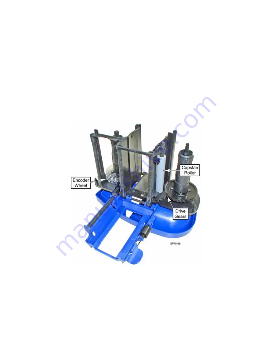
Inspect the spindle and capstan drive gears for wear and missing teeth.
•
Inspect the encoder wheel for missing teeth.
•
Check the spindles for proper movement and to be sure the clutches are
providing a slight drag.
•
Inspect the foil path for nicks or burrs that could damage the foil.
5.
Reassemble the printer.
6.
Wipe the exterior of the printer with a cloth dampened with a non-abrasive,
general purpose cleaning solution. Let the printer dry before connecting
power.
7.
Inspect all sensor to make sure they are properly seated in their mounting
locations.
Summary of Contents for CP80
Page 1: ...Datacard CP80 and CP80 Plus Card Printers Service Manual May 2007 Part No 539490 002 Rev C ...
Page 14: ...1 4 Introduction ...
Page 17: ...CP80 and CP80 Plus Service Manual 2 3 Print Engine Functional Block Diagram ...
Page 18: ...2 4 Theory of Operation Laminator Functional Block Diagram ...
Page 22: ...2 8 Theory of Operation LCD Service Mode Menu Diagram ...
Page 52: ...2 38 Theory of Operation ...
Page 158: ...6 6 Removal and Replacement Print Engine Front Wire Routing Diagram ...
Page 159: ...CP80 and CP80 Plus Service Manual 6 7 Print Engine Duplex and Printhead Wire Routing Diagram ...
Page 160: ...6 8 Removal and Replacement Laminator Front Wire Routing Diagram ...
Page 161: ...CP80 and CP80 Plus Service Manual 6 9 Laminator Rear Wire Routing Diagram ...
Page 162: ...6 10 Removal and Replacement Power Supply Wire Routing Diagram ...
Page 163: ...CP80 and CP80 Plus Service Manual 6 11 Print Engine Cable Connection Diagram ...
Page 164: ...6 12 Removal and Replacement Laminator Cable Connection Diagram ...


