background image

M.A.Ch.10/100 Diagnostic Analyzer 09/00

21

Cable Toolbox

Cable Toolbox lets you run various cable tests with the M.A.Ch.10/100.
You can run a basic cable test that will give you the configuration of the
cable and which device exists at the far end (NIC card, for example), the
cable length, and the wire map results of the cable being tested. In addition,

you can send a tone on the cable or run a Link Test Pulse to the hub or workstation.

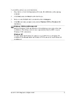
Before running any of these tests, you must plug the cable under test into the
M.A.CH.10/100 device’s 

Cable Test Jack

.

To view the cable test results, or to manually run a cable test, do one of the following:

1. Select 

Cable

 from the 

Tools

 menu.

2. Click the 

Cable Test

 button 

 from the Toolbar menu.

3. Or, click the 

Cable Toolbox

 button.

.

Cable Toolbox Button

Cable Test 

When you run the 

Cable Test

, the M.A.Ch.10/100 displays a wire map showing:


Reversed Wires


Crossed Wires


Open Wires


Shorted Wires


Far End Termination

Running a Cable Test

To run a cable test:

1. Plug the cable you want to test into the 

Cable Jack

 of your H/PC.

2. Click 

Start

. The 

Cable Test 

screen appears. On the right-hand side of this screen,

Wire Map Results

 display.

Summary of Contents for M.A.Ch.10/100

Page 1: ...M A Ch 10 100TM Diagnostic Analyzer ...

Page 2: ... additions to this publication or product at any time without notice Datacom Textron shall not be liable for technical or editorial errors or omissions contained herein Microsoft ActiveSync Windows Windows 95 and Windows NT are either registered trademarks or trademarks of Microsoft Corporation Sony PlayStation is a trademark of Sony Computer Entertainment Inc Other product and company names menti...

Page 3: ...M A Ch 10 100 Diagnostic Analyzer 09 00 iii ...

Page 4: ...purchase By opening the sealed package you agree that the only remedy available will be replacement of defective CD or the correction of the defects submitted in writing as defined above No warranty whether expressed or implied shall apply following the expiration of the 90 day period from the date of original purchase THE WARRANTIES SET FORTH ABOVE ARE IN LIEU OF ANY OTHER WARRANTIES EXPRESS OR I...

Page 5: ... Properties 16 Alarm Settings Properties 17 Toolboxes Menus and Toolbars 18 Three Main Toolboxes 18 Menus 19 Toolbars 20 Cable Toolbox 21 Cable Test 21 Running a Cable Test 21 Wire Map Spec 23 Send Tone 23 Running the Send Tone Test 24 Where to Get a Tone Probe 24 Link Pulse Test 25 Running a Link Pulse Test 25 Port Capabilities 26 TCP IP Toolbox 27 TCP IP Ping 27 Multi Ping 28 Pinging Multiple Ho...

Page 6: ...ewing the Histogram 38 Top Talkers 39 Viewing the Top Talkers Conversations 40 Protocols 42 Determining Network Protocols 42 Errors 43 Performing Error Analysis 43 Station Discovery 45 Discovering Workstation Information 45 Network Discovery 46 Maintenance 48 Reflash 48 Reflashing Your Unit 48 Appendix A 49 Glossary 49 ...

Page 7: ...al level diagnostic features include the Cable Toner and Port Identifier The Cable Toner feature can be used with a Tone Probe for finding cables hidden in walls or for locating the correct cable in bundle The Port Identifier function will blink the Link Test Pulse LTP light on the hub or NIC quickly identifying which port the unit is plugged into Hub and NIC tests can determine the proper operati...

Page 8: ...100 Software To install the M A Ch 10 100 software first connect your H PC to a desktop computer To do this follow the instructions given in your H PC s operator s guide Make sure that you can connect to the device using the Microsoft ActiveSync software If you have problems getting your workstation to communicate with your Windows CE device please contact Microsoft technical support the manufactu...

Page 9: ...n Setup exe 4 Click OK and when prompted select either Windows 95 98 or Windows CE installation Windows 95 98 and Windows CE Both the Windows 95 98 and Windows CE installations can reside on the same workstation This allows you to review captured data from the HP C on your Windows 95 98 workstation Windows NT You can install the Windows CE software to your HP C from a Windows NT workstation but do...

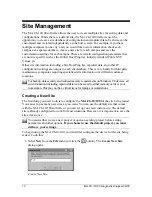
Page 10: ...maintenance companies requiring specialized site information for different customer locations For backup data security and reduced memory requirements on Windows CE devices all site information including captured data can be saved to either memory cards or your workstation This may not be a critical issue for laptops or workstations Creating a New Site The first thing you need to do is to configur...

Page 11: ...in screen displays the new project as the current project M A Ch 10 100 Main Screen You must save each new site at least once to create all of the required database structures used to maintain the site The M A Ch 10 100 software keeps a list of the most recently used sites Current site name is shown ...

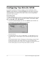
Page 12: ...ted You can select Cable Value NVP Percent Calibrate Units Monitor Report Rate Auto Standby and No Auto Shutdown 1 To access the General Properties tab screen select Options under the Tools menu 2 Click General The General Properties tab screen appears General Tab Screen 3 Under NVP Percent select either the Cable Value or the NVP Value that will be used for this project This information is used w...

Page 13: ...f cable and you would like to determine your own calibration value for a given cable use the calibration feature in this control group to create you own customized value by clicking Calibrate NVP Calibration Screen 5 Enter the actual length of the cable and click Start The M A Ch 10 100 calculates the NVP for this cable 6 Under Units select either Feet or Meters to use in measurements being displa...

Page 14: ...ised to use the AC power adapter for your mobile device 9 Under Auto Standby enter the number of seconds to wait before putting the M A Ch 10 100 in standby mode You can leave the default setting or change it as desired 10 When you are satisfied with your settings click to return to the main screen 11 Click the Save button to make sure your new project settings have been saved Startup Properties S...

Page 15: ... used to start cable station or network diagnostic tests For instance if you normally have to verify the patch cable or other wiring diagnostics you might want to use the button view as your default This allows you to quick get to the cable functions then move to the station diagnostic functions the start the network discovery functions or use other interactive network tests as required Standard V...

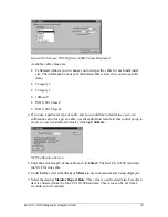
Page 16: ...database and will be automatically configured each time you reopen the site for use If you choose an IP address manually make sure this number fits into your site networking scheme Use the Subnet Design calculator under the IP toolbox if you need help calculating IP address information 1 To access the IP Setup Properties tab select Options under the Tools menu 2 Click IP Setup The IP Setup Propert...

Page 17: ...he Alarm Settings Properties tab select Options under the Tools menu Alarm Settings Tab Screen 2 Click Alarm Settings The Alarm Settings tab screen appears 3 You can set alarms for Utilization Errors and Broadcast You can leave the default settings for now or change them as desired To change each one of these use the or arrows to change the Caution Percent and the Alert Percent values under each o...

Page 18: ...sing the DNS WINS lookup to identify devices on an extended network Duplicate IP address detection quickly identifies workstations that have been assigned the same IP address solving log in and routing problems Ping can be used in a variety of troubleshooting scenarios to identify workstation or port accessibility and location Additionally Ping provides round trip delay information on extended net...

Page 19: ...Exit Exit the M A Ch 10 100 user interface Tools Menu The following options are available on the Tools menu Cable Views the Cable Toolbox dialog TCP IP Views the TCP IP Toolbox dialog where you can perform pings and discover devices Health Views the Health property sheets which show network status and discover workstations or network information Options Views the M A Ch Options property sheets whe...

Page 20: ...ing site database Save Project Saves the current site database Cable Views the Cable Toolbox dialog TCP IP Views the TCP IP Toolbox screen where you can perform tests like ping trace route DHCP look for duplicate IP addresses and view Subnet design information Health Views the Health property sheets which show network status and discover workstations or network information ...

Page 21: ...lug the cable under test into the M A CH 10 100 device s Cable Test Jack To view the cable test results or to manually run a cable test do one of the following 1 Select Cable from the Tools menu 2 Click the Cable Test button from the Toolbar menu 3 Or click the Cable Toolbox button Cable Toolbox Button Cable Test When you run the Cable Test the M A Ch 10 100 displays a wire map showing Reversed Wi...

Page 22: ...t The following screen shows what crossed wires would like When wire pairs are cross wired the screen indicates which pairs were crossed and which ones are straight through Cable Test Returning a Result of Crossed Wires This example shows that a bad cable was detected Cable Test Returning a Result of a Bad Cable ...

Page 23: ...e Cable Toolbox screen Wire Map Spec The Wire Map Spec diagram is a quick reference guide for standard wiring configurations If you know which wiring standard you are using for a particular cable or site a quick look at this diagram will help you determine whether the cable has been properly wired Wire Map Screen Send Tone Send Tone locates wires in the wall individual wire runs in a bundle or tra...

Page 24: ...under test is not plugged into a device i e hub etc 2 Select Cable from the Tools menu of the M A Ch 10 100 3 Click Send Tone The Send Tone screen appears Send Tone Shown Sending Radio Waves Over the Cable Under Test 4 Click Start 5 Click Stop to end the test 6 Click or Cancel to exit the Cable Toolbox screen Where to Get a Tone Probe To acquire a tone probe contact Progressive Electronics 1 800 5...

Page 25: ... by finding the system with the blinking link light The light will blink at about a 1 to 2 second interval This light is located on the NIC card or a headless device such as a print server Running a Link Pulse Test To run the Link Pulse Test 1 Plug one end of the cable you want to test into the Cable Jack of your H PC 2 Click Start The Blink LTP screen appears While the unit is still blinking go t...

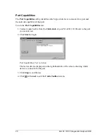
Page 26: ...t To run the Port Capabilities test 1 Connect a patch cable from the Cable Jack of your M A CH 10 100 unit to the port you want to test 2 Click Start to begin Port Capabilities Test in Action The test results are displayed on the right hand side of the screen showing which device is connected to the port 3 Click Stop to end the test 4 Click or Cancel to exit the Cable Toolbox screen ...

Page 27: ... other devices in the field TCP IP Toolbox To access the different tab screens click the desired tab Ping Multi Ping Trace Route DHCP Test Duplicate IP Subnet Design TCP IP Ping Identifies workstations servers gateways and other communications paths 1 Connect one end of cable to the Network Jack of the M A CH 10 100 and the other end to the network segment that you want to test 2 To access the Pin...

Page 28: ...he Average Time field tells gives the average time it took to ping all the devices found If this number is large then you may have routing problems Total Packets shows the total packets found Lost Packets tells you if there were any errors during the Ping test By comparing the difference in these two fields you can discover if you are losing large amounts of data in your network path Average Time ...

Page 29: ...d and saved your Global List or Site List you can then recall the Multi Ping list at anytime and ping multiple devices on your network to test that all hosts are responding properly See Pinging Multiple Devices To ping your selected devices 1 Connect the M A CH 10 100 to a network segment with the appropriate cable connected to the Network Jack of the M A Ch 10 100 board 2 To access the Multi Ping...

Page 30: ...ti Ping List Maintenance Screen 4 If you are creating a new Site List click New List and enter a name for this list in the Current List Name field Be sure to click either Global List or Site List to choose where this list is to be stored 5 Click Save List to save the list 6 Use the Host Name IP Address to Add field to add new names to the current Site List You can either type in the address of the...

Page 31: ...segment with the appropriate cable connected to the Network Jack of the M A Ch 10 100 board 2 To access the Trace Route tab screen select IP under the Tools menu or click the icon 3 Click Trace Route The Trace Route tab screen appears Trace Route Searching for a Communications Path 4 Enter either the Host Name or the Host IP address of the computer whose network route you wish to trace 5 Click the...

Page 32: ... the DHCP tab select DHCP under the Tools menu or click the icon 3 Click DHCP The DHCP property tab screen appears DHCP Test 4 Click the Start button The magnifying glass appears as M A Ch 10 100 sends a packet to locate the addresses of different devices on the network Server IP Issued IP Issued Subnet Mask Issued Gateway Issued DNS and Total Responses The magnifying glass appears as M A Ch 10 10...

Page 33: ...ork segment with the appropriate cable 2 To access the Duplicate IP tab select Duplicate IP under the Tools menu or click the icon 3 Click Duplicate IP The Duplicate IP property tab screen appears Duplicate IP 4 Click the Start button The M A Ch 10 100 reports back on all the IP addresses it located The results display in the Test Results area on the right hand side of the screen Use this list to ...

Page 34: ...ide the network you must go through a gateway This gateway keeps all outside traffic from being seen on your network unless it is addressed specifically to someone on your network It also keeps all of your IP traffic from being seen outside your network unless it is addressed to someone on the outside The following screen shows the M A Ch 10 100 Subnet Designer Start by entering the Host IP Addres...

Page 35: ...gment being changed from 100 to 130 Subnet Design Because 130 is greater than the IP address range for subnet 1 which is 212 132 115 001 to 212 132 115 126 the Network Address and the Broadcast Address have changed to represent the second subnet of our two subnets These are the addresses that are required by any workstation s IP configuration utility IP Addresses as Hex Values You may prefer to vi...

Page 36: ...f the range for your usage planning If you are replaying data from a previous capture these settings will show the data at the time it was captured The level settings green yellow red for these dials are configured in Options under the Tools menu The alarm will sound if only one of these levels settings goes above the set parameter There are three ways to reach the different tests under Network He...

Page 37: ...d Broadcast broadcast rate can be seen by selecting the different options on the screen These options can be individually turned on or off As you select deselect each option the display changes to show only the results you have selected for viewing When only a single option is turned on the corresponding alarm levels will appear as bars on the graph The alarm level settings green yellow and red fo...

Page 38: ...l see alarm and caution bars that coincide with the alarm settings for the other stat types 6 You can use the scroll bar at the bottom of the Histogram to help you locate the source of a problem By looking at the peaks and activity levels you can locate a time period when you are getting high network usage a large count of errors or devices that are broadcasting at too frequently 7 When you have l...

Page 39: ...gain and maintain additional information about any workstation The manufacturer of the network interface is determined by the MAC address that has been registered world wide with the IEEE organization See the www datacom textron com web site for an updated list Understanding MAC Addresses The manufacturer is determined by the first three bytes of the MAC address You can add additional information ...

Page 40: ...ny one or all of the three options Utilization Errors or Broadcast to make the results appear in the Histogram Utilization will appear in blue Errors in yellow and Broadcast in green 6 Click Details The Top Talkers Conversations screen appears Top Talkers Conversations Screen Showing Workstation Resolved The Top Talkers fields show the top workstations those stations generating the most traffic on...

Page 41: ... you to begin building your database of workstations on the network 9 Click Save Name to add the name and the associated information about the workstation to your database 10 Received Time shows the exact time segment that was highlighted on the Histogram screen Stations that were recorded and summarized during the same time frame will appear listed together and the time that they were monitored w...

Page 42: ... 2 it will not be displayed The Network Protocol Analysis dialog displays all network protocols detected by the M A Ch 10 100 along with a pie graph showing the percentages of each protocol in use IPX on 802 3 IPX on 802 2 IPX on Ethernet Type IPX on SNAP IP on 802 3 IP on SNAP NETBEUI Determining Network Protocols From the Network Stats tab screen you can view an analysis of the network protocols...

Page 43: ... error CRC Alignment Code Long Frame Short Frame Late Collision Network Error Analysis Only protocols that have been seen for 2 or more of the total traffic detected and up to the top 5 will be included in the pie chart Anything with a percentage less than 2 does not display separately but is included in the Other total If the Other total is less than 2 it will not be displayed Performing Error An...

Page 44: ...zer 09 00 44 4 As the network is monitored the dial on the dashboard reflects current network utilization 5 Click the Errors button The Network Error Analysis dialog displays 6 Click OK to return to the Network Stats property sheet ...

Page 45: ... server RAS server or Sony PlayStation II Station Discovery Showing Detected Protocols Discovering Workstation Information 1 Attach a patch cable to the Network Jack of the host running the M A Ch 10 100 software to the device you want to find out about Make sure that the device is turned off 2 Click the Station Discovery icon shown above or select Health from the Tools menu and click the Station ...

Page 46: ...nformation 2 Click the Start button to start the discovery process 3 When the discovery is complete click Device View to view the results or click each icon on the Display Map for more information 4 Click the M A Ch 10 100 icon to view version information on software hardware and firmware 5 Click the Cable icon to view cable information 6 Click the Hub icon to view information regarding the hub s ...

Page 47: ... devices that are found when you run Network Discovery These are shown on the right hand of the screen Device Information At the time of this release Novell and Microsoft features are in development Above the list are sort buttons that allow you to sort the information by either Name IP Address or Type ...

Page 48: ...ture of Windows CE Services on your workstation a PCMCIA memory card or a direct download from the web site via your built modem to get the required image file on your device During this process it is imperative that the AC power adapter be used on your mobile device and that you DO NOT interrupt the process once started Reflashing Your Unit The reflash operation is a three part operation To refla...

Page 49: ...rnet coaxial cable It specifies the carrier sense multiple access with collision detection CSMA CD access method on bus topologies Bridge A network device that connects local or wide area networks using the same communications protocols into a single LAN so that data can be transferred from one network to another Broadcast Indicates a message sent across a network to all workstations Broadcast Sto...

Page 50: ... in data transmission by using a complex calculation to generate a number based on the data transmitted The device sending a transmission makes a calculation and sends the result with the transmission The device which receives the transmission compares its own calculation If both results are the same then the transmission is considered error free CSMA CD Carrier Sense Multiple Access with Collisio...

Page 51: ... end of the cable you are testing Fast Ethernet An IEEE standard for running baseband transmissions at 100 Mbps Full Duplex Refers to a communications system or equipment capable of transmission simultaneously in two directions Gateway A gateway is a device connecting networks using different communications protocols This device converts the information into a compatible format so that the informa...

Page 52: ...ackets within and between LANs Issued DNS The original DNS Domain Name System address assigned to a host Issued Gateway The default gateway s IP Address Issued IP The original IP Address assigned to a certain device on a network which uniquely identifies it from all other devices Issued Subnet Mask The original Subnet Mask address assigned to a device on a network Jabber When a device transmits ei...

Page 53: ... MIB describes the objects included in the SNMP agent database SNMP Simple Network Management Protocol agents are sometimes called MIBs These agents either hardware or software monitor the network activity of devices and report this information to the network console workstation Monitor Report Rate This value is used to determine how often data is collected from the M A Ch 10 100 hardware This val...

Page 54: ...andards established to let devices connect and exchange information with a minimum amount of errors These standards specify packet format timing sequencing and error detection Protocol Stack A group of protocols that are stacked above each other in a layered structure are called a protocol stack or protocol suite Each protocol uses the services provided by the lower layer and provides services for...

Page 55: ...ement Protocol SNMP is the network management protocol of TCP IP Subnet A subnet is essentially a network that is a portion of a larger network In order to be called a subnet all devices must have the same IP address See the section on Subnet Design Calculator for more information Subnet Mask The subnet mask is a 32 bit number that is divided into network IDs and Station IDs All workstations on th...

Page 56: ...is a common type of twisted pair cable that does not have a shield wrapped around the wires UDP User Datagram Protocol UDP is the connectionless transport protocol used by SNMP Simple Network Management Protocol UTP Unshielded Twisted Pair UTP cabling has an insulation material similar to that used in phone cabling but it has no extra shielding to protect it from noise It contains at least two con...

Reviews: