

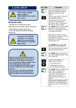
Although the unit is protected against
electromagnetic disturbances, excessive
disturbance can affect the operation,
measurement precision and data
communication quality.
Always remove the plug connectors
when inserting wires with
screwdriver.
Fuses of fast type with a maximum
rating of 6A must be connected to
the power supply and phase voltage
inputs, in close proximity of the unit.
Always refer to National Wiring
Regulations when conducting
installation.
Use cables of adequate current
carrying capacity (at least 0.75 mm
2
).
Use cables of adequed temperature
range.
Use at least 1.5mm
2
cables for
current transformer connection
(AWG15).
The current transformer cable length
should not exceed 1.5 meters. If
longer cable is used, cable section
must be increased proportionally.
Current transformers must have a
5A output.
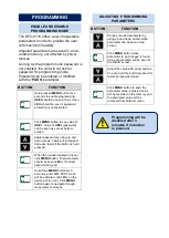
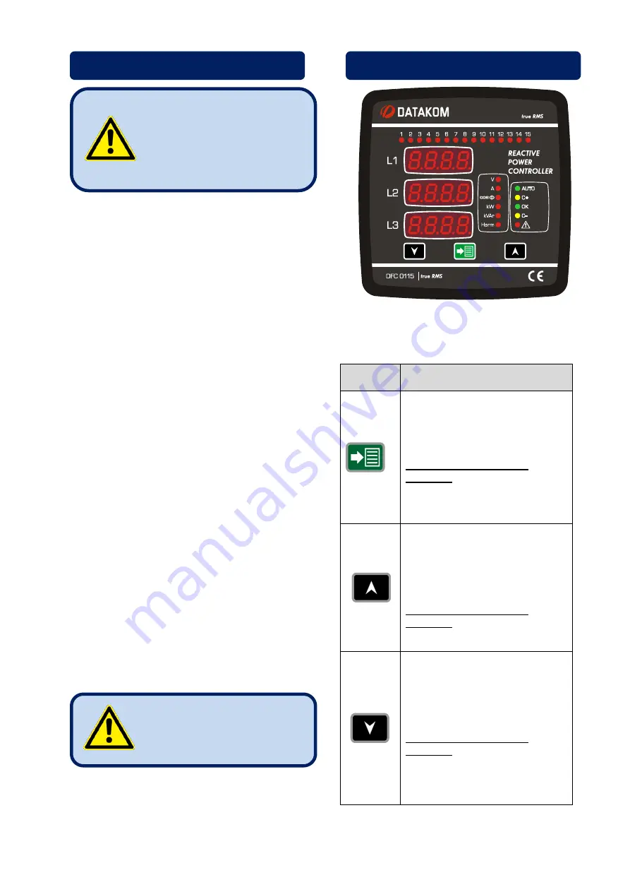
Three buttons on the front panel provide
access to configuration and measurement
screens.
BUTTON
FUNCTION
Remove all alarms in AUTO
mode.
If the same alarm occurs again,
it will not be displayed.
When held pressed for 3
seconds;
Programming mode activated.
All alarms are enabled.
Skip to the next parameter.
(Measurement and parameter
screen)
Increase related parameter.
(Programming screen)
When held pressed for 3
seconds;
Switch on and switch off steps.
Skip to the previous
parameter. (Measurement and
programming screen)
Decrease related parameter.
(Programming screen)
When held pressed for 3
seconds;
AUTO-MANUAL mode switch.
Reactive control is disabled at
MANUAL mode.
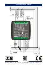
ELECTRICAL CONNECTIONS
Do not place the unit close
to high electromagnetic
noise emitting devices like
contactors, high current
busbars, switch mode
power supplies.
Do not overload relay
outputs. Use extra
contactors if required.
BUTTON FUNCTIONS


