DM4170 – Installation Manual
Installing the DM4170
204.4308.03
24
Step 4
•
Screw the connector to the switch using the same screw that was
removed in step 1.
Table 14 – Steps for the installation of the Protective Grounding
V
ENTILATION
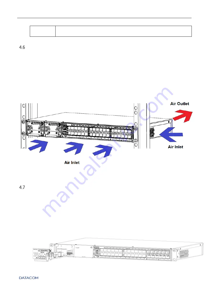
The DM4170 switch ventilation airflow is provided by the inlets on the front and left sides of
the equipment and through the outlets on the rear, as in
. For the
correct operation of the cooling system it is important
that the air inlets and outlets are
unobstructed and that
the free areas of 5cm (2 inches) are respected on the rear panel and
on the left side of the switch. These areas must have free air circulation so that the
temperature of the equipment remains within the assured levels of operation, also observing
the cooling of the environment.
Figure 20 - DM4170 Air Flow
P
RODUCT
P
OWER
S
OURCE
4.7.1
Connecting the PSU 125
The PSU 125 power supplies can be hot-plugged. To connect a PSU to the equipment, align
your printed circuit board with the plastic guides of the slot and insert the card until its panel
touches the equipment panel. Then tighten the knurled screws to ensure correct fixation of
the power supply, as in
. If the slot to be used is
protected by a blind panel, remove it by removing the screws using a Phillips screwdriver.
Figure 21 – Inserting the PSU 125


