DM4170 – Installation Manual
Installing the DM4170
204.4308.03
16
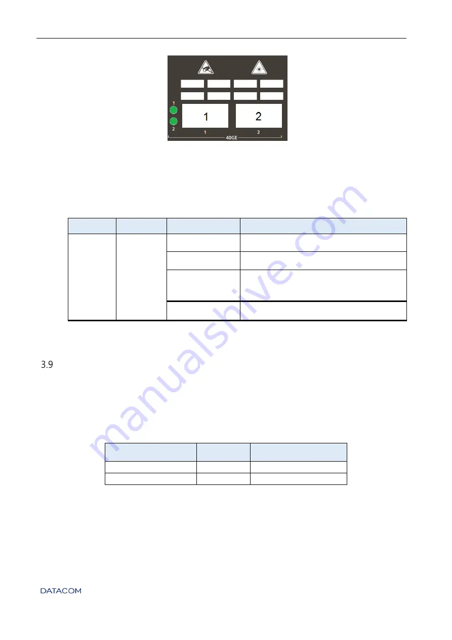
Figure 10 - 40GbE QSFP+ LED ports
3.8.3.1
Indicator LEDs of 40 Gigabit Ethernet optical interfaces
The convention to indicate the operation and mode of operation of the 40GbE QSFP+
interfaces are described in
Indicator
Color
Status
Description
LINK/ACT/
SPEED
GREEN
YELLOW
Off
Link Down (inactive port)
On
GREEN
Link Up at 40Gbps (active port)
On
YELLOW
Link Up operating at a rate lower than
40Gbps
Blinking
Data sending and/or receiving activity
Table 10 – Indicator LEDs of 40GbE QSFP+ interfaces
A
LARM
I
NPUT AND
O
UTPUT
The DM4170 has two alarm inputs and one alarm output in an RJ45 connector.
Alarm 1 and 2
inputs are isolated via optocoupler. External alarm detection occurs when the voltage
difference between IN+ and IN- reaches 12V. Table 10 presents the voltages and status for
alarm 1 and 2 inputs.
Signal IN-
Signal IN+
Description
0V (Reference)
0V to 3V
No alarm
0V (Reference)
12V to 60V
Alarm
Table 11 – Conditions for alarm detection


