DM4170 – Installation Manual
Installing the DM4170
204.4308.03
23
The DM4170 has a label on the rear side of the
mechanics. It contains
model information,
product code and serial number. Check if there is any divergent information
on the label
regarding the information on the packaging.
19-
INCH RACK INSTALLATION
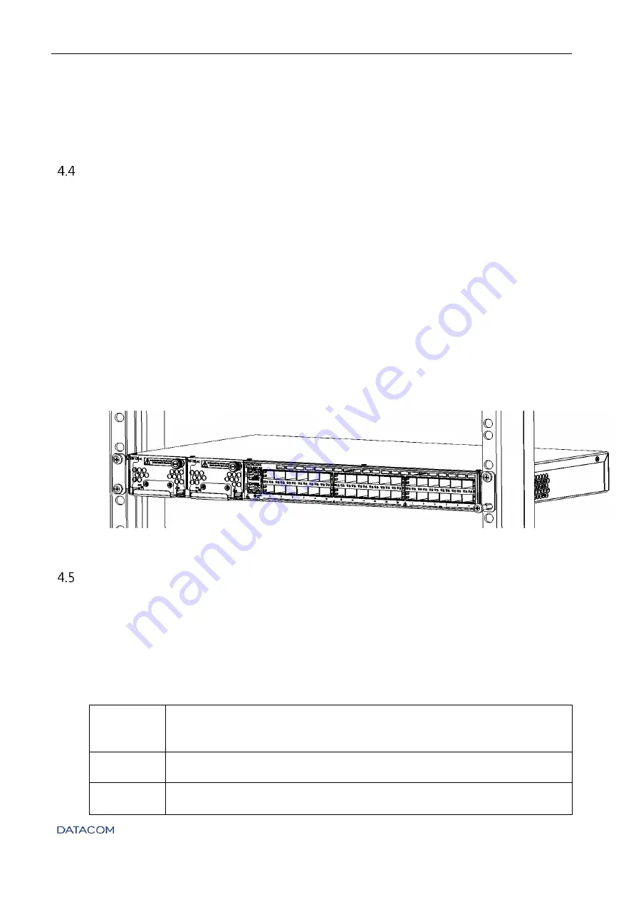
The DM4170 was designed to be installed to 19-inch racks,
occupying only 1U in height. To
choose the suitable installation site, pay attention to the following items:
Choose an easily accessible location where your LEDs can be viewed;
The temperature should be between 0°C and 55°C and the relative air humidity
should be between 10% and 90% non-condensed;
Install the equipment near a power source.
After choosing the appropriate location, bring the equipment to the rack and insert two
standard M5 screws (not shipped with the product) into each side of the adapter to secure
the assembly to the cage nuts on
the rack (not shipped with the product). Finally,
tighten the
screws so as to guarantee that the equipment is securely attached to the rack.
Figure 19 - 19-inch rack installation
C
ONNECTING THE
PROTECTIVE
GROUNDING
The DM4170 has a place on its rear panel to attach a cable to connect the Protective
Grounding.
The grounding cable is not part of the basic accessories shipped with the switch. The cable
indicated for the installation must have a thickness of 10 to 12 AWG. The color of the cable
must follow the specific requirements of the country where the switch will be installed; most
countries determine that the cable should be green with yellow stripes.
Step 1
•
Locate the grounding connector located on the back of the switch as
shown in
Protective
Grounding; remove the connector with a Philips screwdriver.
Step 2
•
Secure the cable to the grounding connector.
Step 3
•
Cut the cable to a length suitable for the connection to the installation
ground.


