System Components
96-30065-001 Rev. A0
DataDirect Networks EF4024 FC RAID System Setup Guide | 11
1.2
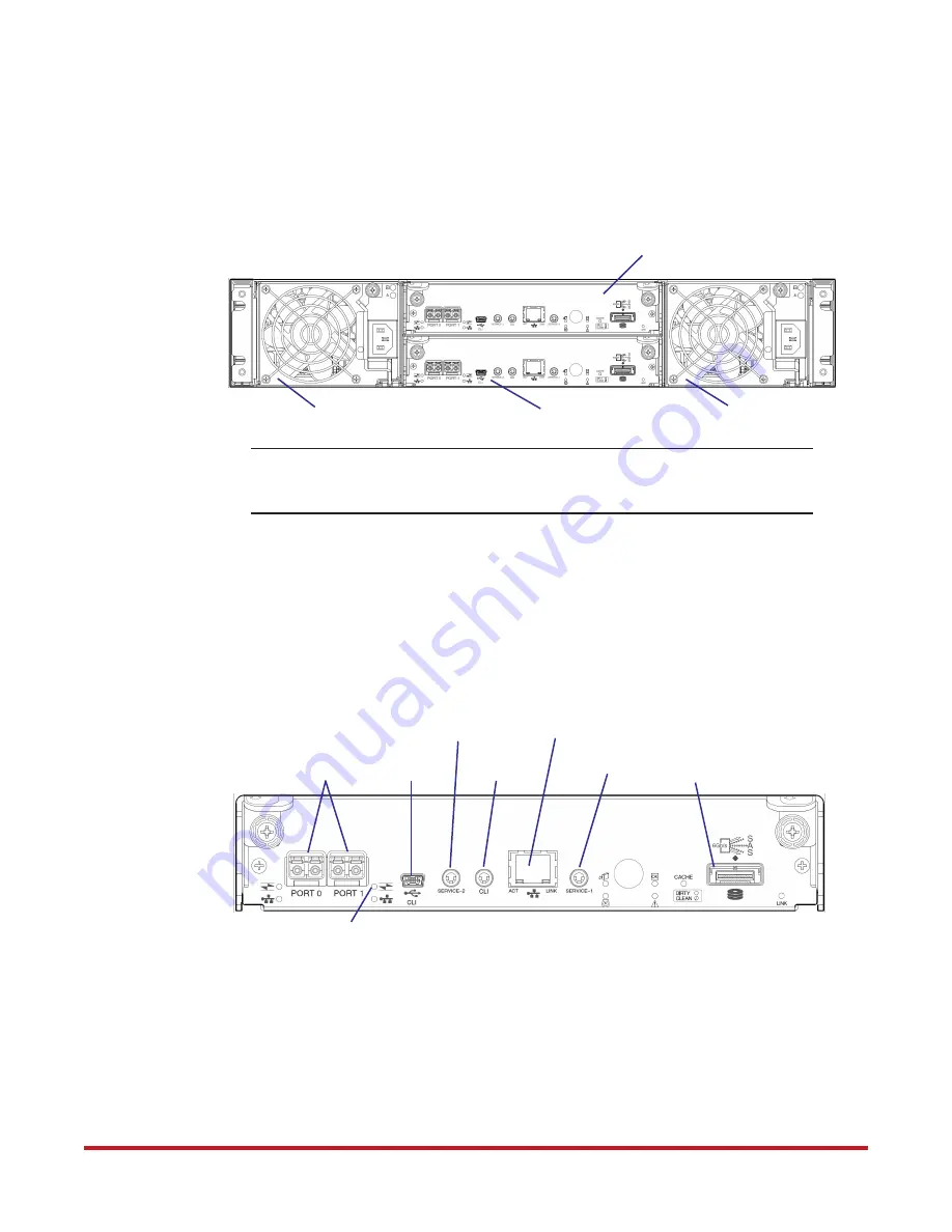
Controller Enclosure Rear Panel
Figure 3
shows the rear panel of the EF4024 controller enclosure. Each controller enclosure
includes two controller modules and two power and cooling modules. Refer to
Appendix A
for LED descriptions.
NOTE :
EF4024 enclosures support hot-plug replacement of redundant controller
modules, power and cooling modules, and expansion I/O modules. Hot-add
replacement of drive enclosures is also supported.
1.2.1
Controller Module
Figure 4
illustrates a controller module. The CNC ports are configured with SFPs supporting
either 8Gb or 16Gb FC connections.
Refer to the
EF4024 RAIDar User Guide
(Configuring Host Ports) for information on CNC
port configuration.
1.2.2
Power and Cooling Module
Power redundancy is achieved through two independent load-sharing power supplies. In the
event of a power supply failure, or the failure of the power source, the storage system can
operate continuously on a single power supply. Greater redundancy can be achieved by
connecting the power supplies to separate circuits.
Refer to
Appendix A
for LED descriptions on power and cooling modules.
Figure 3. Controller Enclosure Rear Panel
Power and Cooling Module
Power and Cooling Module
Controller Module A
Controller Module B
Figure 4. Controller Module
Mini-SAS Expansion Port
CNC Ports for
CLI Port
Host Connections
Service Port 2
(Not Used)
Network Port
Service Port 1
FC LED


