LED indications on front of module
Red LED
Meaning
Output fault
Fast flashing
Internal fault: power supply not
sufficient, out of range offset or
reference. Error on reading or
writing in flash (at the start or on
threshold setting).
Yes
Slow flashing
Dip-switch setting error
Yes
Set threshold in progress
No *
Steady light
Disconnected thermocouple, out
of range input or temperature
compensation
Yes
Output limiting in progress
No
* In this modality the output signal represents the value of the threshold.
Yellow LED
Meaning
ON
The auxiliary output is closed
OFF
The auxiliary output is open
0.2 to 2.5mm
2
8mm
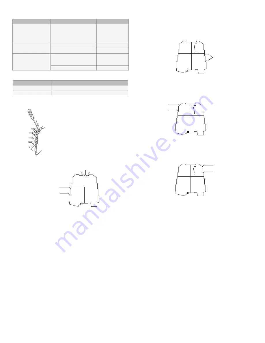
Electrical connections
The module is designed for spring cage clamp
electrical connections.
1. Strip cables by 0.8mm.
2. Insert screwdriver in the square hole and press
until the cable lock spring opens.
3. Insert cable in the round hole.
4. Remove screwdriver and ensure cable is tightly
fastened in the terminal.
Power supply
There are three ways to power the DSCP6x series of signal converters.
1. Connect the 24VDC power supply directly to terminals 7 (+) and 8 (-)
of each module.
2. Connect power to one signal converter and use the expandable Power-
Bus connector to distribute power to a maximum of 16 adjacent modules.
The bus can be supplied from any of the modules, but the total current
consumption of the bus must be less than 400mA. Higher consumption
values can damage the module. An appropriately sized fuse must be
connected in series with the power supply.
3. Use the DSCP70 Power Supply Connection Module and the expandable
Power-Bus connector to distribute power to a maximum of 75 modules.
The DSCP70 is designed to protect the modules connected via bus against
overvoltage loads. The bus connector can be provided with power using the
DSCP70 module if the total consumption of the bus is less than 1.5A. Higher
consumption values can damage both the module and the bus. An appropri-
ately sized fuse must be connected in series with the power supply.
1
2
3
4
5
6
7
8
+
-
19.2 to 30VDC
Power
supply
Set threshold
Red LED
Yellow LED
Input
The module accepts input from the following types of thermocouples:
J, K, R, S, T, B, E, N.
The use of shielded cables is recommended for the electronic connections
1
2
3
4
5
6
7
8
Output
Input
+
TC
Power
supply
Output: Voltage / Current connections
The use of shielded cables is recommended for the electronic connections.
1
2
3
4
5
6
7
8
Output
Input
Power
supply
+
-
V / I
1
2
3
4
5
6
7
8
Output
Input
Power
supply
AUX
AUX
1
2
3
4
5
6
7
8
Output
Input
Power
supply
+
-
V / I
1
2
3
4
5
6
7
8
Output
Input
Power
supply
AUX
AUX
Auxiliary output
The auxiliary output is designed to drive an indicator, a relay of greater
power, or the input of a supervisory control system.
Dataforth Corporation
3331 E. Hemisphere Loop • Tucson, AZ 85706 USA • Toll Free: 800-444-7644 • Tel: 520-741-1404 • Fax: 520-741-0762 • Email: sales@dataforth.com •
www.dataforth.com
SD1145 02/11
©
2011 Dataforth Corporation, All Rights Reserved ISO9001:2008 Registered QMS
3


