DPR-400 User Manual Rev_01 Firmware V-1.0
- 16 -
Structure:
Isolated, integrated current transformers
Measurement Method:
True RMS
Sampling Rate:
8192 Hz
CT Secondary Rating:
1 or 5A
CT Range:
5/5 - 30000/5A minimum
Measurement Range:
Measurement inputs: 0.01 - 6A AC
Protection inputs: 0.1
– 250 A AC
Display resolution:
0.1A
Accuracy:
0.5% + 1 digit
Isolation:
1000VAC/1minute from all other terminals.
Maximum Current:
20A continuous
Withstanding:
500A for 1sec
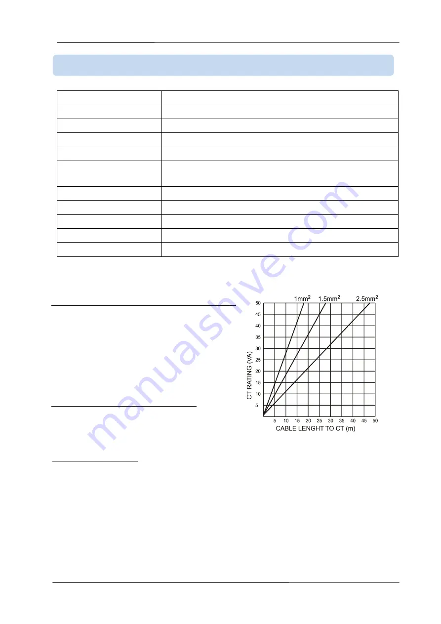
SELECTING THE CT RATING AND CABLE SECTION:
The load on a CT must be kept minimum in order to
minimize phase shift effect of the current transformer.
Phase shift in a CT will cause erroneous power and
power factor readings, although the amp readings are
correct.
It is advised CT rating to be selected following this table
for the best measurement accuracy.
SELECTING THE CT ACCURACY CLASS:
The CT accuracy class should be selected in accordance
with the required measurement precision. The accuracy
class of the controller is 0.5%. Thus 0.5% class CTs are
advised for the best result.
CONNECTING THE CTs:
Be sure to connect each CT to the related phase input with the correct polarity. Mixing CTs between
phases will cause faulty power and power factor readings.
Many combinations of incorrect CT connections are possible, so check both the order of the CTs and
their polarity. Reactive power measurement is affected by incorrect CT connections in a similar was as
active power measurement.
3.3. AC CURRENT INPUTS


