i50 Manual (5.51)
Page 52
© 2018 Datalink Systems, Inc.
www.datalinksystemsinc.com
11.0 Internal Wi-Fi (version 3.x PCB)
The internal Wi-Fi module can be configured in two ways: as an access point, or as a client. In either
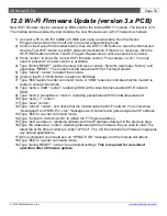
case, ensure that the “Port A Route” setting is set to “Wi-Fi” to enable communications with the Wi-Fi
module.
11.1.1 Create Access Point
In this mode, the module creates a software access point using the SSID and passphrase
programmed into settings
, and creates a listening TCP socket using the port defined under the “Wi-Fi
Port” settings.
The Wi-Fi module will periodically broadcast its status using a UDP packet sent to port 55555. This
packet is 110 bytes long, and contains
the text “WiFly” starting at the 61
st
byte. The 9
th
and 10
th
bytes
contain the listening TCP port number (most significant byte first). Connected devices can use this
packet to detect the i50’s IP address and listening port.
To send data, devices
will connect to the i50’s SSID, and then open a TCP/IP connection to the i50.
It is expected that the normal use for this mode will be to program the i50 port A to “Messages”,
allowing devices to send and receive messages or check i50 status remotely.
Note: to ensure reliability, the i50 will reset the Wi-Fi access point if no device connects for 10
minutes, or a device is connected but no TCP data is received for 10 seconds. Therefore it is
recommended to send some data every few seconds while connected to maintain the link.
11.1.2 Connect to Network
The internal Wi-Fi module can also be used to connect to an external Wi-Fi network, using the
programmed SSID and passphrase
. Once connected, the i50 will attempt to look up the server’s IP
address using the domain name (if programmed), and then create a UDP socket to that IP address.
The normal use for this mode will be to program the i50 port A to “Wi-Fi”, allowing the i50 to
communicate directly to the server.


