MECHANICAL DIMENSIONS
PRODUCT REFERENCE GUIDE 45
MECHANICAL DIMENSIONS
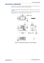
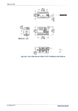
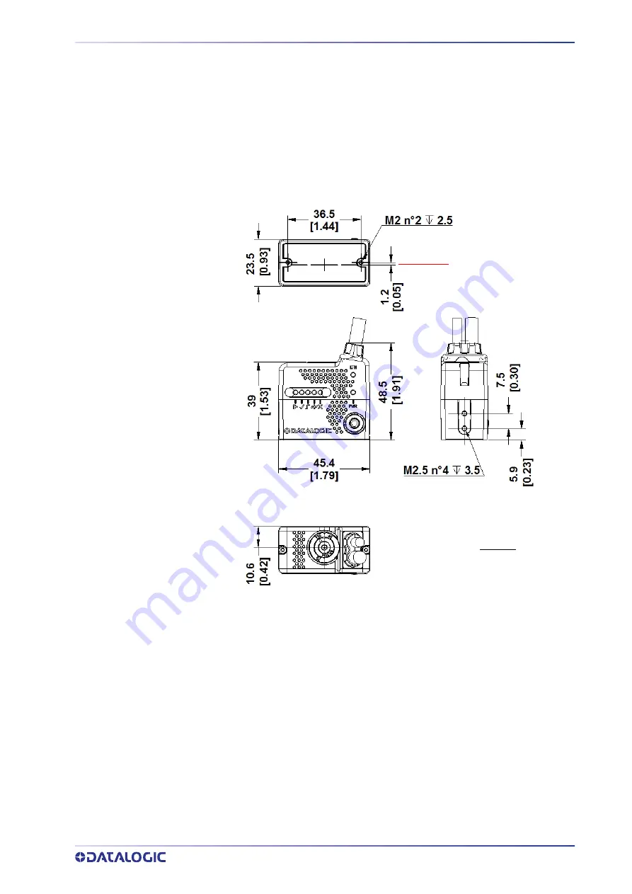
Matrix 120™ can be installed to operate in different positions. The two screw holes on
the body of the reader are for mechanical fixture (Figure 25).
The diagrams below give the overall dimensions of the reader and may be used for its
installation.
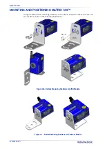
Refer to page 50 for various mounting solutions and correct positioning, and
for FOV vs. Reading Distance considerations.
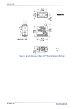
mm
[in]
Optical Axis
Figure 25 - Overall Dimensions of Matrix 120™ Ethernet Models
Summary of Contents for 937800000
Page 1: ...Matrix 120 PRODUCT REFERENCE GUIDE Image Based Reader ...
Page 14: ...GENERAL VIEW XIV MATRIX 120 ...
Page 75: ...INPUTS PRODUCT REFERENCE GUIDE 61 Figure 41 NPN External Trigger Using Matrix 120 Power ...
Page 97: ...GLOBAL FOV DIAGRAMS PRODUCT REFERENCE GUIDE 83 Matrix 120 310 xxA Models Digimarc Barcode ...
Page 153: ...Reader 2 Reader 3 PASS THROUGH CONFIGURATIONS PRODUCT REFERENCE GUIDE 139 ...
Page 185: ......
Page 186: ......
Page 187: ......


