background image

Department 
TSS L3 LM 

Classification 

Public


Page 11  18/04/2019 


Version 

1.0 

Date 
4/18/2019 


Page 11/27 

© 2019 Datalogic S.r.l – All Rights Reserved 


8.


Now the Outbound rule must be set, making sure that all connection would be 
allowed also  in  an  Output  direction.  Basically,  the  procedure  must  be  repeated 
from point 2 to point 9, selecting ‘Outbound Rules’ at point 2 of the procedure. 
Once this is done, the created input and output rules will be seen along with all 
the other firewall rules. 


Once  all  these  settings  have  been  entered,  in  order  to  make  them  permanent  on  the 
Laser Marking System, please double click on the ‘Save-Data.bat’ icon, present on the 
Desktop of the Laser Marker. 
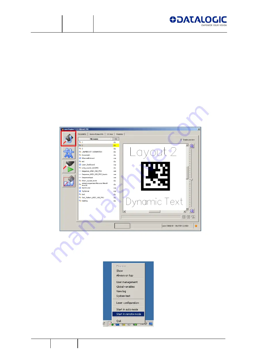
At this point, to activate ProfiNet/IO communication on the Datalogic Laser Marker side, 
it  is  sufficient  to  set  Laser  Engine  in  Remote  Mode,  by  clicking  on  the  indicated  Push 
Button from the Laser Engine GUI: 

 
In order to have the Laser Engine starting in Remote Mode also after the Laser Marker 
has rebooted, click ‘Start in remote mode’ from the Laser Engine icon in the Windows 
tray bar. 


Summary of Contents for Arex 420

Page 1: ...Datalogic Lighter built in ProfiNet I O for Laser Marking Systems Installation and User Manual April 2019 REVISION 1 0 ...

Page 2: ...3 LM Classification Public Version 1 0 Date 4 18 2019 Page 2 27 2019 Datalogic S r l All Rights Reserved Master Revision History Revision Date Author s Change Description 1 0 18 04 2019 M Pierpaolini Beta Site Release ...

Page 3: ... of the Laser Marker 7 2 2 CONFIGURING THE SIEMENS S7 1200 CONTROLLER FOR USE OVER PNIO 13 Creating a PNIO node using the GSDML file 13 Configuring the Laser Marker PNIO node on TIA Portal 15 CYCLIC COMMUNICATION BETWEEN THE PLC AND THE DATALOGIC LASER MARKING 3 SYSTEM 16 3 1 INPUT ASSEMBLY MEMORY MAP 18 Description of the Input Assembly Memory Map 19 3 2 OUTPUT ASSEMBLY MEMORY MAP 20 Description ...

Page 4: ...a reference for the creation of this User Manual were made using the following versions of HW and SW Element used Versioning PLC Siemens S7 1200 CPU 1214C DC DC DC Article no 6ES7 214 1AG31 0XB0 Firmware rev 3 0 PLC programming SW tool TIA Portal v 13 SP1 Datalogic Laser Marker Arex430 Lighter version Lighter 7 2 0 Alpha 8 Datalogic S r l recommends to read this User Manual carefully before perfor...

Page 5: ...Name and make changes to the Firewall Rules moreover the User according to his application will have to choose the dimension of the Input and Output Memory Areas These changes are described in the following paragraphs Basic net settings of the Laser Marker The Datalogic Laser Marking systems can be discovered on an ProfiNet IO network only if a number of parameters on the Laser Marker and on the P...

Page 6: ...alogic S r l All Rights Reserved c The size of the Input and Output Memory Maps has to be set also inside the Profinet section choosing from the 3 possible sizes expressed in Bytes 64 128 or 254 d Once these parameters have been set press Apply followed by OK on the bottom of the Interface ...

Page 7: ... to establish a ProfiNet IO connection between the PLC and the Laser Marker the user can either completely disable the control of the Windows Firewall or allow all Inbound and Outbound traffic regarding LaserEngine exe To create these Inbound and outbound rules regarding the Windows Firewall the User can follow this procedure on the Laser Marker 1 Enter the Control Panel and select Advanced settin...

Page 8: ... 0 Date 4 18 2019 Page 8 27 2019 Datalogic S r l All Rights Reserved 3 A Wizard GUI will guide you through the procedure select Program 4 In the Program And Services tab browse towards the LaserEngine exe application present in C ProgramFiles Lighter 7 2 ...

Page 9: ...Department TSS L3 LM Classification Public Version 1 0 Date 4 18 2019 Page 9 27 2019 Datalogic S r l All Rights Reserved 5 Select Allow the connection then press Next ...

Page 10: ...Department TSS L3 LM Classification Public Version 1 0 Date 4 18 2019 Page 10 27 2019 Datalogic S r l All Rights Reserved 6 Select all 3 types of Network 7 Give this property a recognizable name ...

Page 11: ...een along with all the other firewall rules Once all these settings have been entered in order to make them permanent on the Laser Marking System please double click on the Save Data bat icon present on the Desktop of the Laser Marker At this point to activate ProfiNet IO communication on the Datalogic Laser Marker side it is sufficient to set Laser Engine in Remote Mode by clicking on the indicat...

Page 12: ...c Version 1 0 Date 4 18 2019 Page 12 27 2019 Datalogic S r l All Rights Reserved When in Remote Mode the Laser Engine GUI will look like this having all the Push Buttons disabled except for the one which brings Laser Engine back to Local Mode ...

Page 13: ...ject it is necessary to install the GSDML file Once the new ProfiNet IO node has been imported inside the project there are some parameters which need to be set before starting to work on the data exchange between the PLC and the Laser Marker Creating a PNIO node using the GSDML file Select the Manage general station description files GSD from the Options Menu Now follow the steps in order to inst...

Page 14: ...device from the HW catalog under this filepath Other field devices PROFINET IO General Datalogic S r l Laser Marker LASER MARKER 1P To do so drag drop the device from the Hardware Catalog into the HW configuration of the device Once you have imported the device into the HW configuration of your project you will need to link it to the PLC which will communicate with the Datalogic Laser Marker Drag ...

Page 15: ...Marker PNIO node choose the size 64 128 and 254 Bytes of the Input and or Output Memory Maps A new Device Name can be entered in the Module properties in the section General Name Regarding Input and Output Memory sizes users will be able to check the dafult size of both areas 254 bytes from the Device Overview if the user wants to change such memory sizes he can cancel the default settings from th...

Page 16: ...n the Input and Output Assembly Memory Map Command Bit single bit part of a group of bits which are present on the Output Assembly Memory Map and according to its position it will represent the command which the PLC wants the Laser Marker to execute Mirroring Bit single bit part of a group of bits which are present on the Input Assembly Memory Map and according to its position it will inform the P...

Page 17: ... State Diagram As soon as the connection is established the State diagram is positioned at its Entry Point the protocol will not accept any command from the PLC before receiving an Output Assembly Memory Map fully made of 0 Until this condition is fulfilled the If the Command Bit has changed state 1 0 as soon as the EXECUTING state has been reached then the State Diagram will stay in EXECUTING sta...

Page 18: ...turn to 0 when the command is ended The Protocol State will pass in LISTENING as soon as the Command Executing bit passes 1 0 3 1 Input Assembly Memory Map The input Assemby Memory Map has been developed in order to structure all the data coming from the Datalogic Laser Marker towards the PLC Depending on the information that the Laser is returning at every Update Time the PLC could need to check ...

Page 19: ...tocol is not currently in this phase 1 Protocol is currently in this phase Lighter is executing a command 1 Command Error Lighter has generated a Command Error Check address 4 for the Command Error Code 2 Protocol Error Lighter has generated a Protocol Error Check address 5 for the Protocol Error Code 3 7 Protocol Boot Up Lighter PNIO is in BOOTING UP phase it will end as soon as a completely empt...

Page 20: ... to 7 Response Data Size Low Byte Response Data field usable length Low and High byte Reporting the PLC how long the usable data is inside the Response Data field 55 0 to 7 Response Data Size High Byte 56 to 63 127 253 0 to 7 for each address Byte Response Data Each byte represents an ASCII character that the laser is reporting towards the PLC From Address 56 for a number of bytes specified by the...

Page 21: ... From Device 0 1 Asking to load an XLP 1 0 as soon as the mirroring bit is HIGH Loads the document specified in the Request Data Field xlp extension must be included the document must be in the Laser Engine default filepath D Data Docs Layouts 1 Save Document 0 1 Save current document 1 0 as soon as the mirroring bit is HIGH Overwrites the current xlp file 2 Get Data Field value 0 1 Gets the conte...

Page 22: ... 1 Move Data Field 0 1 Moves the specified Data Field to the position specified inside Request Data Field 1 0 as soon as the mirroring bit is HIGH Moves the laser object with a specified ID to the specified position The movement is done considering the object s origin Request Data Field FieldID LF X Y 5 to 53 Reserved 54 0 to 7 Request Data Size Low Byte Response Data field usable length Low and H...

Page 23: ...a routine which will manage these errors Command Error A Command Error is notified to the PLC when the requested command cannot be executed In addition to the single Command Error notification bit a whole byte address 4 of the Input Assembly Memory Map describes the reason of such an error The values which address 4 can have when a Command Error is notified are summed up in the following table Val...

Page 24: ...mory area Command Error are not blocking errors which request an acknowledgement from the PLC after that any kind of Command Error is reported the PLC will be able immediately request a new command to the Laser Marker which will try to execute it normally Protocol Error A Protocol Error is notified to the PLC when the Laser Marking System is not able to correctly determinate a single command to ex...

Page 25: ...fied in case 1 2 and 3 it is necessary for the PLC to set the Protocol Error Clear bit Address 1 bit 7 which sets the Protocol back into LISTENING state This operation will not work if the value returned by the Protocol Error is point 4 in this case the ProfiNet IO connection must be closed and then re established between the Laser System and the PLC ...

Page 26: ...rrors and the Event Tracking depending on the selected tab when the Event Tracing is selected the user can check the details of each command which the Laser Marker has executed via ProfiNet IO By clicking on the button in the4 Details column the user can find the Data and the reported length which was either necessary to execute the command present on the Request Data area or the data which has be...

Page 27: ...Department TSS L3 LM Classification Public Version 1 0 Date 4 18 2019 Page 27 27 2019 Datalogic S r l All Rights Reserved Format is the following Length Data ...

Reviews: