PRODUCT REFERENCE GUIDE
191
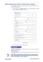
Modify Settings | Device Settings | <Camera Name> | Mounting
Use the
Mounting
window when installing and calibrating the camera.
To view the Mounting window:
1. In the menu tree under Modify Settings, navigate to
Device Settings | <Camera
Name> | Mounting.
The
Mounting
window opens.
2. View the following barcode reader information
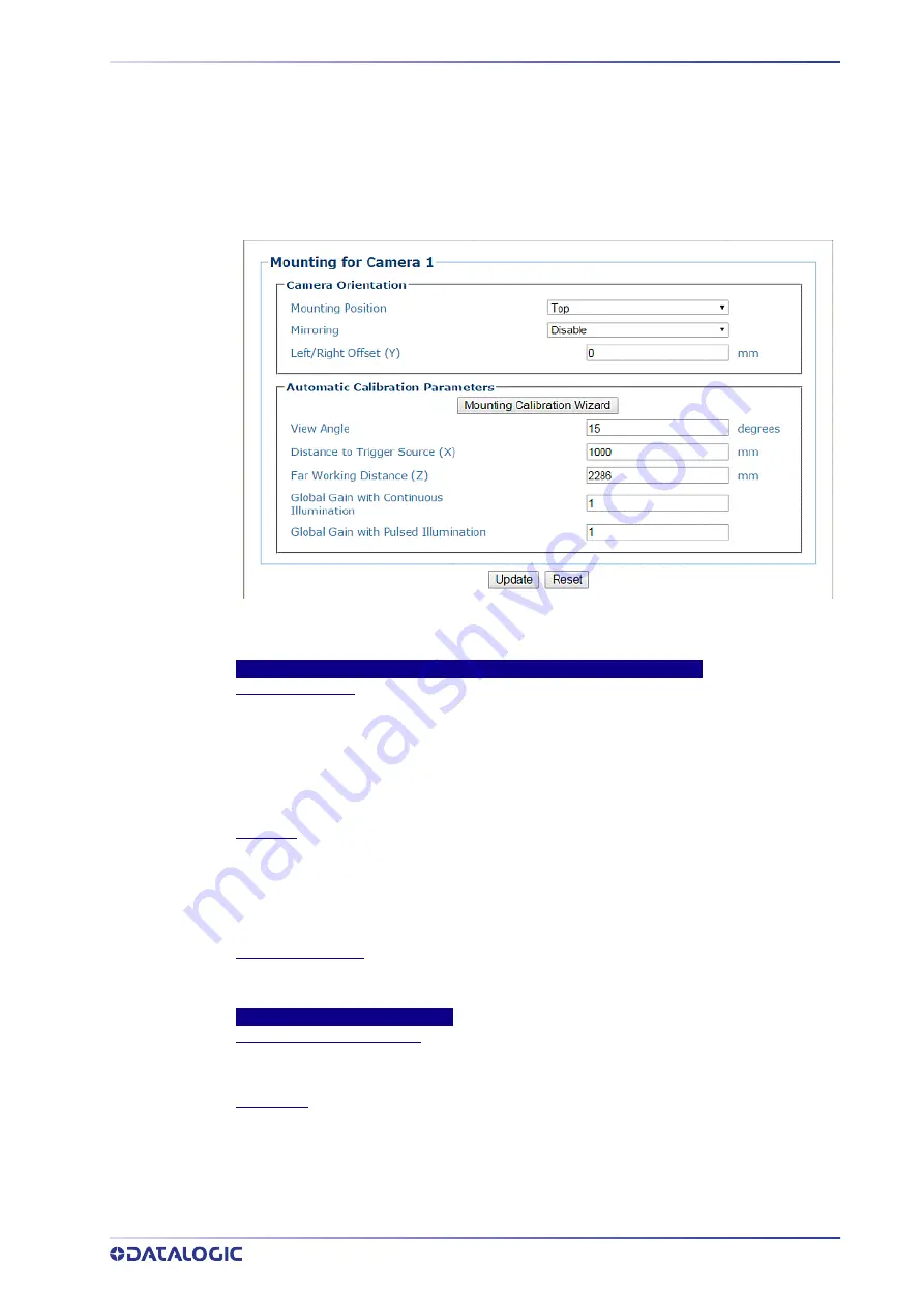
Camera Orientation
Mounting Position
Select
Top, Left, Right,
or
Bottom
from the drop-down list depending on where the camera is
mounted.
This parameter allows defining the installation position of the camera in multi-camera tunnel
installations according to the code reading on the conveyor: Top, Right, Left, etc. This
parameter acts on the software reading algorithms and on the position and height sensors
configuration.
Mirroring
Select
Disable
or
Enable
from the drop-down list.
This parameter (when enabled) allows inverting or mirroring the image sent by the camera.
This function is used to set the object movement with respect to the camera mounting position
(i.e. camera position = Top Back). It is used to change a reversed (mirrored) image to proper
orientation for OCR applications or video coding.
Left/Right Offset (Y)
Enter the camera offset from the Y-axis. 0 = centered on Y. This defines the center of the
cropped image.
Automatic Calibration Parameters
Mounting Calibration Wizard
Click to open the Mounting Calibration Wizard (see section ). This is used during initial static
calibration only.
View Angle
Enter an angle (degrees) in the field provided.
This parameter allows defining the reading angle of the camera. For standard installations this
angle should be set to match the mechanical mounting: +15 or -15 degrees (single side object
reading), +45-degrees for a side/back read or -45-degrees for a side/front read (double side
object reading) depending on the type of installation. This parameter may be up to two
degrees different then the 15/45 degree after the completed calibration.
Summary of Contents for AV7000
Page 1: ...AV7000 PRODUCT REFERENCE GUIDE Linear CAMERA...
Page 48: ...MECHANICAL INSTALLATION 34 AV7000 LINEAR CAMERA...
Page 49: ...INSTALLATION SEQUENCE PRODUCT REFERENCE GUIDE 35...
Page 55: ...INSTALLING THE DEFLECTION MIRROR PRODUCT REFERENCE GUIDE 41...
Page 57: ...INSTALLING THE DEFLECTION MIRROR PRODUCT REFERENCE GUIDE 43...
Page 60: ...MECHANICAL INSTALLATION 46 AV7000 LINEAR CAMERA...
Page 66: ...ELECTRICAL INSTALLATION 52 AV7000 LINEAR CAMERA Controller Client Array with DM3610...
Page 69: ...TYPICAL CONNECTION BLOCK DIAGRAMS PRODUCT REFERENCE GUIDE 55 AV7000 in Hybrid Configuration...
Page 80: ...ELECTRICAL INSTALLATION 66 AV7000 LINEAR CAMERA Photoelectric Sensor to CBX510 PNP...
Page 96: ...ELECTRICAL INSTALLATION 82 AV7000 LINEAR CAMERA Unpowered Outputs...
Page 97: ...CBX100 CBX510 CBX800 INITIAL CONFIGURATION PRODUCT REFERENCE GUIDE 83 Powered Outputs...
Page 116: ...E GENIUS 102 AV7000 LINEAR CAMERA...
Page 134: ...E GENIUS 120 AV7000 LINEAR CAMERA...
Page 175: ...PRODUCT REFERENCE GUIDE 161 4 Again run the small package through the system...
Page 239: ...PRODUCT REFERENCE GUIDE 225 12 Click Update to save your changes...
Page 278: ...FOCUSING SETUP AND CALIBRATION 264 AV7000 LINEAR CAMERA...
Page 309: ...READING LINEAR BARCODES PRODUCT REFERENCE GUIDE 295 READING LINEAR BARCODES...
Page 310: ...AV7000 FEATURES 296 AV7000 LINEAR CAMERA...
Page 311: ...PRODUCT REFERENCE GUIDE 297...
Page 312: ...AV7000 FEATURES 298 AV7000 LINEAR CAMERA...
Page 313: ...PRODUCT REFERENCE GUIDE 299 READING 2D BARCODES...
Page 314: ...AV7000 FEATURES 300 AV7000 LINEAR CAMERA...
Page 315: ...PRODUCT REFERENCE GUIDE 301...
Page 316: ...AV7000 FEATURES 302 AV7000 LINEAR CAMERA...
Page 336: ...TROUBLESHOOTING 322 AV7000 LINEAR CAMERA 4 Click Stop Acquiring to freeze the scope...
Page 350: ...TECHNICAL FEATURES 336 AV7000 LINEAR CAMERA...
Page 351: ......

