background image


01 

DATALOGIC S.p.A., 

Via Candini, 2 

40012 - Lippo di Calderara 

Bologna - Italy 

dichiara che 
declares that the 
déclare que le 
bescheinigt, daß das Gerät 
declare que el 

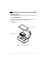
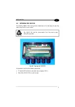
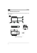
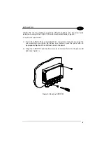
C-BOX 100, passive connection box 

e tutti i suoi modelli


and all its models 


et tous ses modèles 


und seine modelle 


y todos sus modelos 

 
sono conformi alle Direttive del Consiglio Europeo sottoelencate: 
are in conformity with the requirements of the European Council Directives listed below: 
sont conformes aux spécifications des Directives de l'Union Européenne ci-dessous: 
der nachstehend angeführten Direktiven des Europäischen Rats: 
cumple con los requisitos de las Directivas del Consejo Europeo, según la lista siguiente: 
 

89/336/EEC EMC Directive

 e 

92/31/EEC, 93/68/EEC 

 emendamenti 

successivi


and 


further 

amendments 


et 


ses successifs amendements 


und 


späteren 

Abänderungen 


succesivas 

enmiendas 

 
Basate sulle legislazioni degli Stati membri in relazione alla compatibilità elettromagnetica ed alla sicurezza dei prodotti. 
On the approximation of the laws of Member States relating to electromagnetic compatibility and product safety. 
Basée sur la législation des Etates membres relative à la compatibilité électromagnétique et à la sécurité des produits. 
Über die Annäherung der Gesetze der Mitgliedsstaaten in bezug auf elektromagnetische Verträglichkeit und Produktsicherheit 
entsprechen. 
Basado en la aproximación de las leyes de los Países Miembros respecto a la compatibilidad electromagnética y las Medidas 
de seguridad relativas al producto. 
 
 
Questa dichiarazione è basata sulla conformità dei prodotti alle norme seguenti: 
This declaration is based upon compliance of the products to the following standards: 
Cette déclaration repose sur la conformité des produits aux normes suivantes: 
Diese Erklärung basiert darauf, daß das Produkt den folgenden Normen entspricht: 
Esta declaración se basa en el cumplimiento de los productos con las siguientes normas: 


EN 55022, August 1994

: L

IMITS AND METHODS OF MEASUREMENTS OF RADIO DISTURBANCE CHARACTERISTICS OF 

INFORMATION TECHNOLOGY EQUIPMENT 

(ITE) 


EN 50082-2, March 1995

: E

LECTROMAGNETIC COMPATIBILITY

. G

ENERIC 

I

MMUNITY 

S

TANDARD

. P

ART 

2: I

NDUSTRIAL 

ENVIRONMENT


Lippo di Calderara, 07/03/2001 


Ruggero Cacioppo 


Quality Assurance Supervisor 


Summary of Contents for C-BOX 100

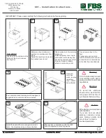
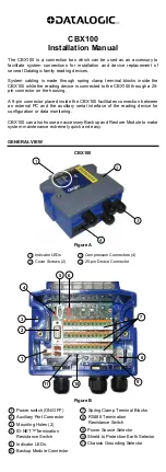
Page 1: ...C BOX 100 Installation Manual...

Page 2: ...C BOX 100 Installation Manual...

Page 3: ...C BOX 100 INSTALLATION MANUAL...

Page 4: ...thout prior notification Datalogic shall not be liable for technical or editorial errors or omissions contained herein nor for incidental or consequential damages resulting from the use of this materi...

Page 5: ...ATION 2 2 1 Package Contents 2 2 2 Opening the Device 3 2 3 Mechanical Installation 4 2 4 Electrical Connections and Setup 6 2 4 1 Power Supply 7 2 4 2 System Wiring 8 2 4 3 Chassis Grounding Jumper S...

Page 6: ...ation in the section Safety Precautions at the beginning of this manual 2 Correctly position and mount the C BOX 100 within the reach of the barcode scanner cable according to the information in parag...

Page 7: ...v GENERAL VIEW C BOX 100 2 1 3 Figure A 25 pin scanner connector Cover screws 4 Compression connectors 1 2 3...

Page 8: ...is grounding selector 3 20 mA C L connector 5 4 Power on LED green Power Polarity Error LED red 6 Scanner selection switch Auxiliary port connector 7 OM4000 jumpers 8 Termination resistance switch 9 S...

Page 9: ...o be supplied by an NEC Class 2 power source rated 10 30 V minimum 0 50 A CAUTION The overall value of power consumption of the system C BOX 100 scanner is given by adding the scanner power consumptio...

Page 10: ...viii...

Page 11: ...vided through spring clamp terminal blocks inside the C BOX 100 The scanner is connected to the C BOX 100 through a 25 pin connector placed on the left side of the housing A 9 pin connector placed ins...

Page 12: ...KAGE CONTENTS Verify that the C BOX 100 and all the parts supplied with the equipment are present and intact when opening the packaging the list of parts includes 1 C BOX 100 2 Installation manual 1 2...

Page 13: ...to open it by unscrewing the four cover screws CAUTION The C BOX 100 must be disconnected from the power supply during this operation Figure 2 Opening the C BOX 100 It is possible to perform the follo...

Page 14: ...C BOX 100 4 2 2 3 MECHANICAL INSTALLATION The diagram below gives the overall dimensions of the C BOX 100 and may be used for its installation Figure 3 Overall Dimensions...

Page 15: ...gure 4 To mount the C BOX 100 1 Open the C BOX 100 by unscrewing the 4 cover screws If necessary using the two mounting holes inside the device as a pattern mark the panel with an appropriate object a...

Page 16: ...he internal spring clamp connectors After making system cabling and switch settings see sub paragraphs under 2 4 connect the scanner to the 25 pin connector on the left side of the C BOX 100 housing S...

Page 17: ...th the C BOX 100 and the connected scanner S1 ON OFF Figure 6 Power Switch ON OFF Positions C BOX 100 1 2 VS GND USER INTERFACE GND V 10 30 Vdc Figure 7 Power Supply Connections NOTE Pin 1 is also ele...

Page 18: ...e the individual wires of the system cables by stripping the insulation back approximately 1 cm Using a device such as a screwdriver push down on the lever directly next to the clamp see Figure 8 Inse...

Page 19: ...SA SGND AUX NC GND GND 39 SGND SGND SGND GND GND DS2100 DS2400 DS4300 DS4600 A DS6XXX MATRIX 2XXX DS1100 DS2200 MATRIX 1XXX RS232 RS485FD RS485HD 20mA CL RTX485HD 11 15 TX232 TX485 RTX485 CLOUT RTX485...

Page 20: ...rs SGND MAIN is internally connected to the GND through a filtering circuit 2 4 3 Chassis Grounding Jumper Settings The scanner chassis grounding method can be selected by positioning a jumper see Fig...

Page 21: ...esistance Switch The switch S2 enables or disables the insertion of the bus termination resistor for RS485 Half Duplex Multidrop applications CAUTION In Multiplexer applications the termination resist...

Page 22: ...terminals for applications which use the OM4000 Oscillating Mirror in Trigger Mode They are used together and have the following significance when a jumper is in the J1 position see Figure above pin 4...

Page 23: ...re indicated in the following table Figure 13 9 pin Male Connector 9 pin connector pinout Pin Name Function 1 N C 2 RXA Auxiliary RS232 3 TXA Auxiliary RS232 4 N C 5 SGND Signal Ground 6 N C 9 N C DS2...

Page 24: ...0 g 11 29 oz ENVIRONMENTAL FEATURES Operating temperature 10 to 50 C 14 to 122 F Storage temperature 20 to 70 C 4 to 158 F Humidity max 90 non condensing Vibration resistance IEC 68 2 6 test FC 1 5 mm...

Page 25: ...s of Member States relating to electromagnetic compatibility and product safety Bas e sur la l gislation des Etates membres relative la compatibilit lectromagn tique et la s curit des produits ber die...

Reviews: