INSTALLATION
15
2
2.6
CONFIGURATION SWITCH AND 9-PIN INTERNAL CONNECTOR
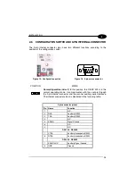
The 9-pin internal connector may have two different functions according to the
position of the configuration switch.
Figure 15 - Configuration switch
Figure 16 - 9-pin male connector
POSITION
MODE
Normal Operation
(default): In this position, the C-BOX 3X0 is in the
normal operating mode. It communicates with the scanner through
the 9-pin internal connector and the scanner auxiliary serial interface.
The internal connector pinout is illustrated in the following table:
9-pin connector pinout
Pin
Name
Function
1
N.C.
2
RXA
Auxiliary RS232
3
TXA
Auxiliary RS232
4
N.C.
5
SGND
Signal Ground
6
N.C.
9
N.C.
DS2100 - DS2400
7
CTSA
Auxiliary Handshake RS232
8
RTSA
Auxiliary Handshake RS232
DS4300 - DS4600
7
SGND AUX
Auxiliary Signal Ground
8
GND
Ground


