CBX800 INSTALLATION MANUAL
22
INPUTS
The two optocoupled polarity insensitive inputs, Input 1 (External Trigger Input) and Input 2, a generic input,
available on the CBX800 spring clamp terminal blocks, are managed by the reader connected to the 25-pin
connector.
These inputs are optocoupled and can be driven by both NPN and PNP type commands.
NOTE
Polarity insensitive inputs assure full functionality even if pins A and B are exchanged.
External Trigger Input (Input 1)
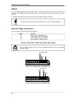
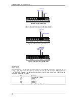
The connections are indicated in the following diagram:
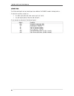
Pinout
Function
+V
Power Source - External Trigger
I1A
External Trigger A (polarity insensitive)
I1B
External Trigger B (polarity insensitive)
-V
Power Reference - External Trigger
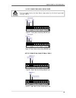
EXTERNAL TRIGGER INPUT CONNECTIONS USING CBX800 POWER
CAUTION
Power is available directly to the Input Device, independently from the Power Supply Switch
inside the CBX800.
(brown)
(black)
(blue)
PH-1 Photocell (PNP)
Figure 27 – PH-1 External Trigger Using CBX800 Power
Power to
Input
Photocell Signal
Photocell
Reference
NPN Photocell
Figure 28 - NPN External Trigger Using CBX800 Power


