CBX800
INSTALLATION
MANUAL
7
MECHANICAL INSTALLATION
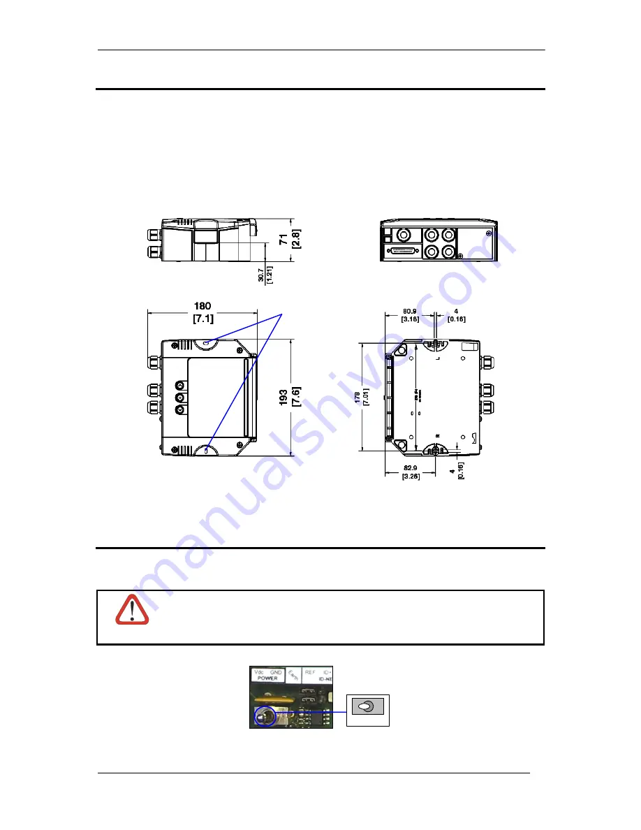
CBX800 can be mounted to various wooden or plastic surfaces using two self-threading screws (3.9 x 45 mm) and
washers.
Mounting to other surfaces such as concrete walls or metallic panels requires appropriate user-supplied parts
(screws, screw anchors, nuts, etc).
CBX800 can also be mounted to a DIN rail or a Bosch Frame using the following mounting accessories: BA100
(93ACC1821), BA200 (93ACC1822).
The diagram below gives the overall dimensions of the CBX800 and shows the two mounting through-holes.
Figure 3 - Overall Dimensions
POWER SUPPLY
The power switch (see Figure 4) switches the power supply ON or OFF for both the CBX800 and the connected
reading device.
CAUTION
The power switch does not control power to the Vdc/GND, +V/-V spring clamps, therefore
any devices connected to these signals (i.e. external trigger, encoder, etc.), are live and are
not protected from polarity inversion. Disconnect the power supply when working inside the
CBX800.
OFF
ON
Figure 4 - Power Switch ON/OFF Positions
Mounting
Holes


