DATALOGIC
DS41
Installation - 2.21
2.7.4 Inputs
The inputs available on the DS41 scanner are the pins relative to the code
presence sensor, as indicated below:
Pin
Name
Function
18
PS+
Presence sensor (input+)
19
PS-
Presence sensor (input-)
The inputs indicated are always used to connect the code presence sensor
which tells the scanner to scan for a code. The yellow led (Figure A,
5
) is
on during the active phase of the PS signal indicating that decoding can take
place.
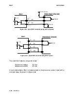
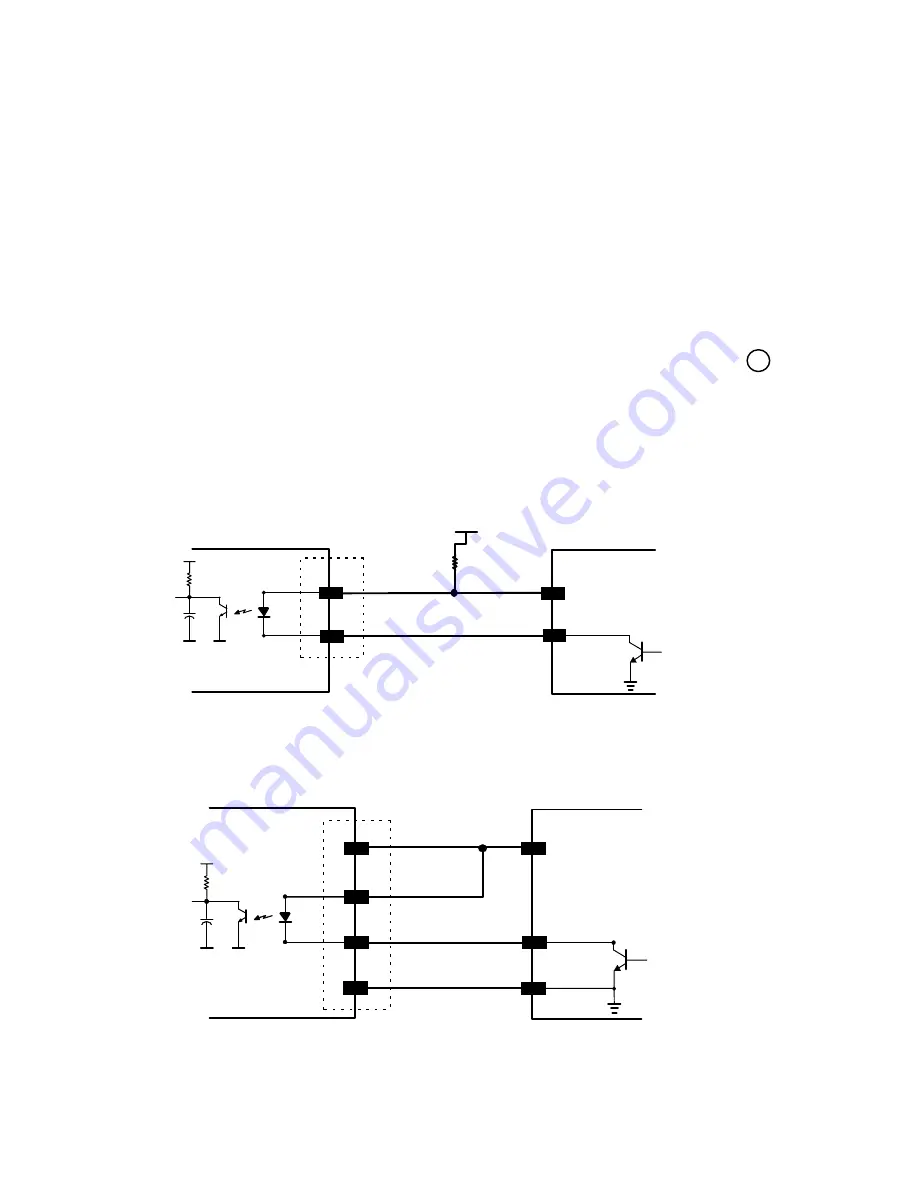
This input is optocoupled and can be driven by both an NPN or PNP type
command. The connections are indicated in the following diagrams:
PRESENCE SENSOR
DS41
30 Vdc max.
Vext
PS+
PS-
18
19
+ 5V
Signal
V
Figure 2.23 - Input NPN command using external power
PRESENCE SENSOR
DS41
Signal
PS+
PS-
18
19
+ 5V
VS
9
25
GND
Ground
V
Figure 2.24 - Input NPN command using DS41 power


