DS5100 REFERENCE MANUAL
70
4
The output signals are fully programmable being determined by the configured
Activation/Deactivation events, Deactivation Timeout or a combination of the two.
The electrical features of the outputs are the following:
V
CE
= 30 Vdc max.
I
CE
= 40 mA continuous max.; 130 mA pulsed max.
V
CE saturation
= 1 Vdc max. @ 10 mA
P
D
= 90 mW Max. @ 50 °C ambient temp.
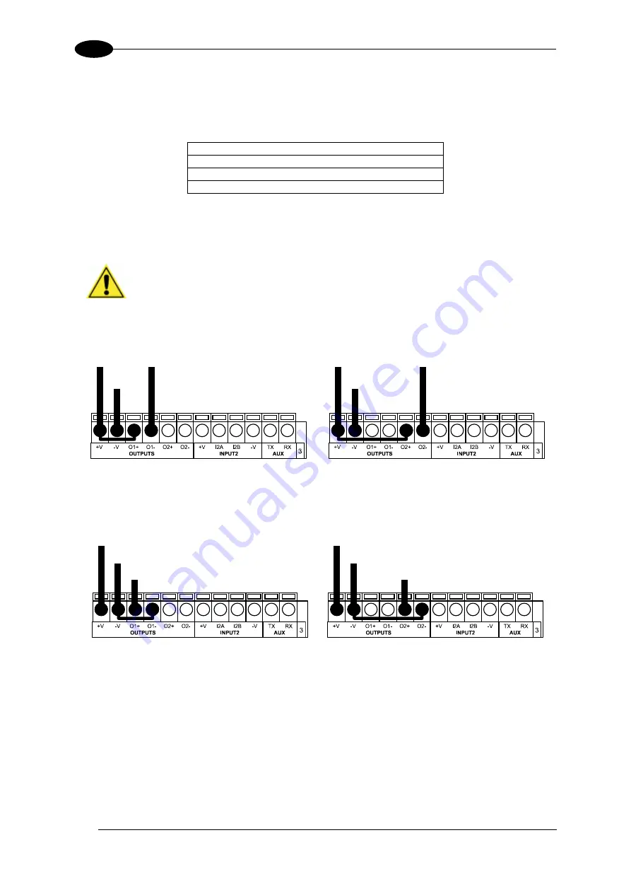
OUTPUT 1 AND 2 CONNECTIONS USING SCANNER POWER
CAUTION:
Power from the Vdc/GND spring clamps is available directly to
the Output Device on the +V/-V spring clamps, and does not pass through
the Power Switch (ON/OFF) inside the CBX. Disconnect the power supply
when working inside the CBX.
Figure 49 - PNP/Open Emitter Output Using Scanner Power
Figure 50 - NPN/Open Collector Output Using Scanner Power
Power to
Output
Output device
Signal
Output device
Reference
Output 1 Device
Power to
Output
Output device
Signal
Output device
Reference
Output 2 Device
Power to
Output device
Output device
Reference
Output 1 Device
Output
Signal
Power to
Output device
Output device
Reference
Output 2 Device
Output
Signal
Summary of Contents for DS5100
Page 1: ......
Page 30: ...DS5100 REFERENCE MANUAL 14 1 b Digital Outputs configuration c Hardware interface selection...
Page 62: ...DS5100 REFERENCE MANUAL 46 3 Figure 18 DS5100 OM Serial Model Overall Dimensions...
Page 78: ...DS5100 REFERENCE MANUAL 62 4 Figure 38 ID NET Network Connections with isolated power blocks...
Page 97: ...TYPICAL LAYOUTS 81 5 7 Double click on the DS5100 scanner to configure it...
Page 163: ...147 X X PRESS Human Machine Interface 23...
Page 164: ......


