DS6400 QUICK GUIDE
12
OSCILLATING MIRROR MODEL
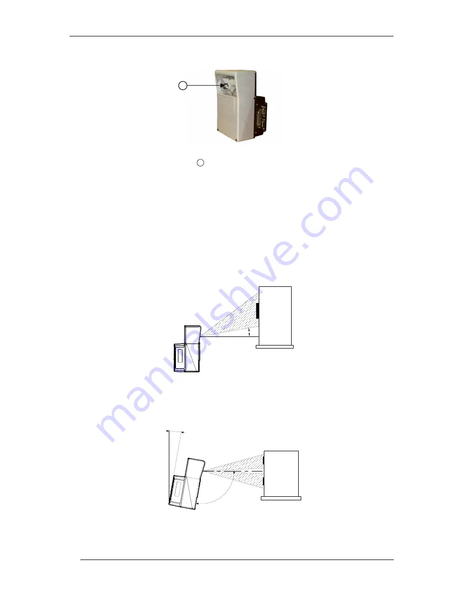
Figure A
Laser Beam Output Window
1
Oscillating mirror models are used when coverage of a large reading area is required, mainly in picket fence
applications.
The DS6400 scanner mounts a dedicated optic head with integrated oscillating mirror driven by a linear motor.
The speed, precision, repeatability, and reliability of this driving technology assure high level performance.
The new oscillating mirror is completely software controlled and software programmable. The Genius™ software
tool allows adjusting the linear motor speed (oscillating frequency) and the upper and lower limits of the oscillation
by defining the top and bottom line limit angles.
When the oscillating mirror is programmed to read barcode labels at very small angles, position the reader to
assure at least 10°
for the Skew angle (see DS6400 Reference Manual). This angle refers to the most inclined or
external laser line, so that all other laser lines assure more than 10° Skew. This avoids the direct reflection of the
laser light emitted by the reader.
10
°
Oscillating Mirror Skew Angle
Otherwise, the scanner can be mounted at an angle of inclination of 17.5° in order to attain symmetrical deflection
ranges.
17.5°
10
7.
5°
Oscillating Mirror Reading Position
In the above case, the zone where the scan line is perpendicular to the reflecting surface corresponds to a neutral
zone at the center of the reading field.
1


