INSTALLATION
23
2
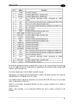
Pin Name
Function
1 GND
Ground
(chassis)
2
AUX IN -
Auxiliary digital input (negative pin)
3
AUX IN +
Auxiliary digital input (positive pin)
4 N.C.
Not connected (optionally factory configured as COM1
GND)
5
N.C.
Not connected (optionally factory configured as COM1 RX)
6
PS -
Presence sensor signal (negative pin)
7
N.C.
Not connected (optionally factory configured as COM1 TX)
8 N.C.
Not
connected
9
24 Vdc
Power supply
10
PS+
Presence sensor signal (positive pin)
11
COM3 GND COM3 reference ground
12
AUX OUT + Auxiliary digital output (positive pin)
13
24 Vdc
Power supply
14
ENC +
Optical encoder signal (positive pin)
15
ENC -
Optical encoder signal (negative pin)
16
COM3 TX-
COM3 transmit data –
17
COM3 TX+ COM3 transmit data +
18
COM3 RX-
COM3 receive data -
19
COM3 RX+ COM3 receive data +
20
N.C.
Not connected (optionally factory configured as COM2 TX)
21
N.C.
Not connected (optionally factory configured as COM2 RX)
22
0 Vdc
24 Vdc reference ground
23 N.C.
Not connected (optionally factory configured as COM2
GND)
24
AUX OUT - Auxiliary digital output (negative pin)
25
0 Vdc
24 Vdc reference ground
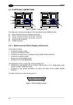
Normally the DC9500 Controller supplies correct power to the camera through the CAB-X05
(5 mt.) or CAB-X10 (10 mt.) cable and also redistributes the external sensor signals (light
curtains, optical encoder etc.).
For further details refer to the DC9500 Controller manual.
Alternatively, the camera can be connected to a C-BOX 100 passive junction box using the
CAB-6005 (5 mt.) or CAB-6010 (10 mt.) cable.
The DV9500 camera should be powered by an external 24V±10% DC source. The Camera
power consumption is 30 W max.
COM3 is a full duplex, optoisolated RS422 port and is usually connected to an height or
distance sensor.
COM1, when available, is an optoisolated RS232 port and is usually connected to the
decoder.
Summary of Contents for DV9500 Series
Page 1: ...DV9500 Installation Manual ...
Page 2: ......

