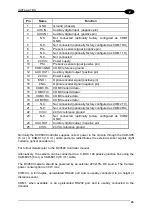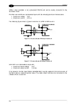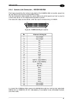
INSTALLATION
25
2
2.6.2 Camera COM1 – Decoder Communication and Configuration
The camera COM1 serial port is an opto-isolated RS232 interface that allows:
•
connection to the Host PC
•
connection to Genius™ software configuration program
•
camera boot loader access for emergency procedures
This port can be redirected on the main connector as a factory configuration.
The same port can also be redirected on the Camera Link serial port using a software
configuration option.
In both cases the COM1 9-pin connector is isolated.
When COM1 is redirected to the camera link output, with the standard application software,
the “USER DEF” LED is switched on.
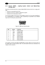
To connect the COM1 camera port to the DC9500 Controller use serial cable CAB-9205 (5
mt.) or CAB-9208 (8 mt.) or CAB-9210 (10mt.). Alternatively, it is possible to use a shielded
9-pin male to female pin-to-pin serial cable.
5
1
9
6
Figure 22 - COM1 9-pin Female Connector
Pin Name
Function
1 N.C.
Not
connected
2 TXD
Transmit
data
3 RXD
Receive
data
4 N.C.
Not
connected
5 GND
Signal
ground
6 N.C.
Not
connected
7 N.C.
Not
connected
8 N.C.
Not
connected
9 N.C.
Not
connected
If not present, a ferrite (type Stewart 28A2029-0A0) must be applied on the camera side of
the COM1 cable to reduce electrical noise. The cable shield must also be connected to the
chassis of both connectors.
Summary of Contents for DV9500 Series
Page 1: ...DV9500 Installation Manual ...
Page 2: ......


