DV9500
28
2
2.6.5 LVDS Connectors – VIDEO1/VIDEO2
The image acquired by the camera is provided on the VIDEO1 and VIDEO2 connectors
present on the rear panel of the LVDS DV9500 models.
These connectors provide an LVDS parallel output.
Based on an internal configuration, both 16-bit and 32-bit outputs are available.
In the 16-bit output configuration, VIDEO1 and VIDEO2 connectors share exactly the same
signals and can be used to connect the camera to two independent acquisition systems.
In the 32-bit output VIDEO1 transmits the lower 16-bits while VIDEO2 transmits the upper
ones.
In BCR applications a 16-bit output is selected by default and Datalogic provides a cable to
connect VIDEO1/2 to the frame grabber inside the PC Decoder.
To connect the LVDS signals to the DD9500 Decoder use LVDS cable CAB-9005 (5 mt.) or
CAB-9008 (8 mt.). Alternatively, it is possible to use a double shielded Standard LVDS cable
with the shield connected to ground at both connectors.
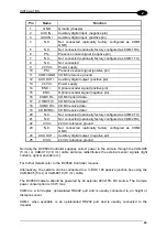
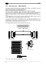
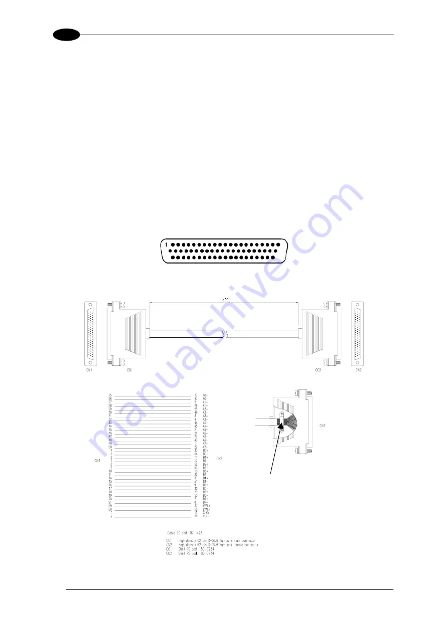
The following table describes the video cable pinout and structure.
Figure 25 – LVDS Connector
Shield connected to the shell
Frame grabber connector
Camera connector
The “+” and “-“ wires of the same signal must be twisted.
Summary of Contents for DV9500 Series
Page 1: ...DV9500 Installation Manual ...
Page 2: ......


