DV9500
52
4
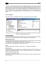
For a correct functioning of the system, it is fundamental that the side margin corresponds
overlaps as much as possible to the package angle demarcating the two sides. To do this,
adjust the distance value in "Distance (mm)" parameter, in the Position Sensor folder. It is
also necessary to perform some acquisition with packages of different heights and check if
the side margin always corresponds to the package angle. If not, the view angle is not
correct, therefore it is necessary to adjust the "View Angle (deg)" value in the Optical Setup
folder.
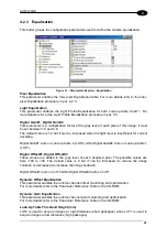
4.2.6 Sensors
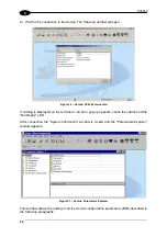
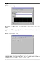
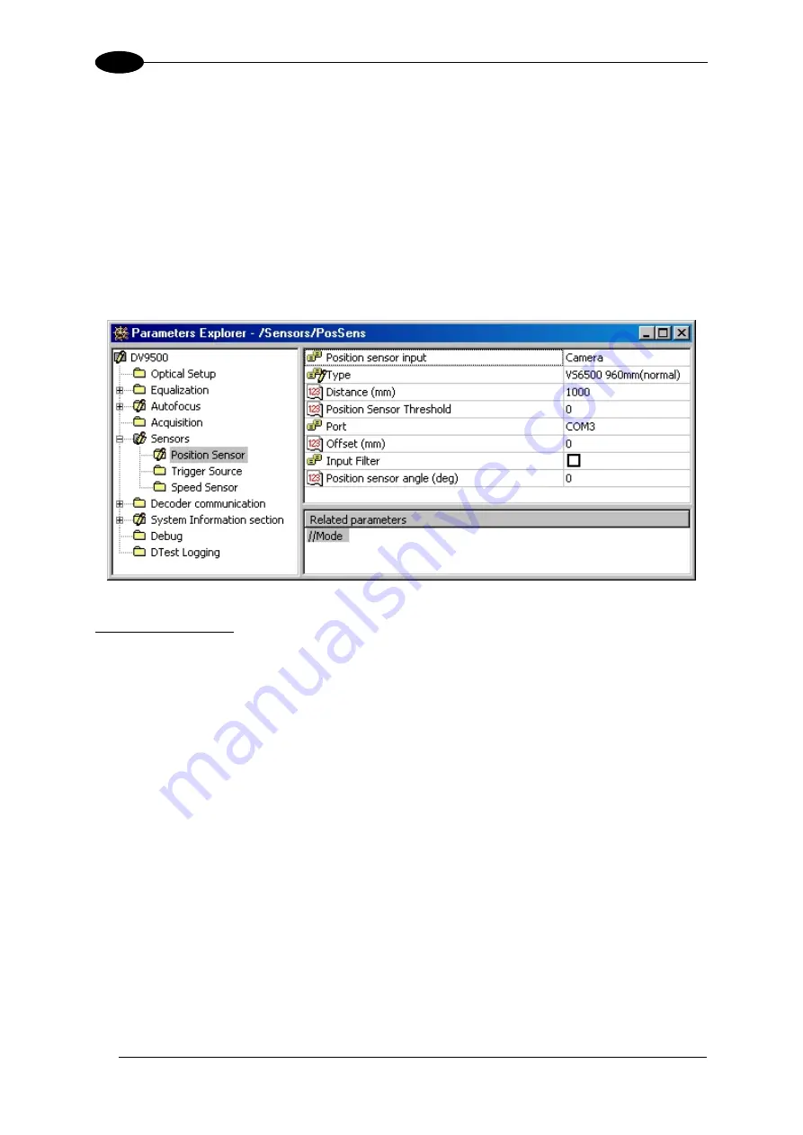
This folder groups the configuration parameters regarding camera external sensors:
Figure 44 – Parameters Explorer: Sensors
POSITION SENSOR
In this section the settings relative to the position sensor are stored. Visible only in D/Power
Pass Through, Single Camera, Master Camera, Slave Camera operating modes.
Position Sensor Input
This parameter allows selecting the position sensor input. If the position sensor is directly
connected to the camera through the serial cable, select "Camera".
If the information from the position sensor to the camera comes through the PC Decoder,
select "Decoder". (see Master-Slave configuration, par. 2.6.3).
Type
This parameter allows selecting the sensor model (i.e. Height barriers: VS6500).
Distance (mm)
This parameter indicates the distance from the position sensor to the camera view line. It is
possible to precisely set this value using the procedure described for the "Image Marker"
parameter in the Acquisition folder.
Position Sensor Threshold (mm)
This parameter specifies the threshold under which the sensor output is zero and the camera
does not acquire.
Summary of Contents for DV9500 Series
Page 1: ...DV9500 Installation Manual ...
Page 2: ......

