background image

iv

   DWS-SWITCH-MONO

PREFACE

ABOUT THIS MANUAL

This Instruction Manual is provided for users seeking advanced technical information,

including installation, connections, maintenance and specifications.

Manual Conventions

The symbols listed below are used in this manual to notify the reader of key issues or

procedures that must be observed:

TECHNICAL SUPPORT

Support Through the Website

Datalogic provides several services as well as technical support through its website. Log

on to (www.datalogic.com).
For quick access, from the home page click on the search icon , and type in the name of

the product you’re looking for. This allows you access to download Data Sheets, Manu

-

als, Software & Utilities, and Drawings.
Hover over the Support & Service menu for access to Services and Technical Support.

Reseller Technical Support

An excellent source for technical assistance and information is an authorized Datalogic

reseller. A reseller is acquainted with specific types of businesses, application software,

and computer systems and can provide individualized assistance.

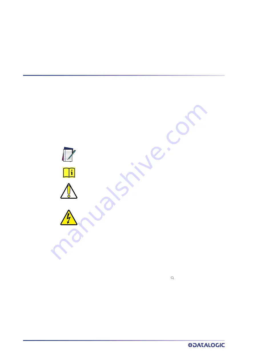
NOTE: This symbol draws attention to important details or procedures that

must be followed for the correct installation of the product.

INFORMATION: This symbol used on the label, refers the user to informa

-

tion contained in this manual.

CAUTION: This symbol identifies a hazard or procedure that, if incorrectly

performed,  may  cause  personal  injury  or  result  in  equipment  damage.

Operations carrying this symbol must be performed by qualified personnel

only.

HIGH VOLTAGE: This symbol alerts the user they are about to perform an

action involving, either a dangerous level of voltage, or to warn against an

action that could result in damage to devices or electrical shock.

Summary of Contents for DWS-SWITCH-MONO

Page 1: ...L DWS SWITCH MONO INSTALLATION MANUAL AC Power Disconnector and Distributor...

Page 2: ...ll notices appear on any reproductions of the documentation Electronic versions of this document may be downloaded from the Datalogic website www data logic com If you visit our website and would like...

Page 3: ...l Support iv Safety Regulations v Electrical Safety v Product Label v CE Compliance v General View vi CHAPTER 1 INTRODUCTION 1 CHAPTER 2 INSTALLATION 2 Cabinet Mounting 2 System Wiring AC Output 3 Sys...

Page 4: ...ces and Technical Support Reseller Technical Support An excellent source for technical assistance and information is an authorized Datalogic reseller A reseller is acquainted with specific types of bu...

Page 5: ...c promptly adopts these updates therefore the EU declaration of conformity is a living document The EU declaration of conformity is available for competent authorities and customers through Datalogic...

Page 6: ...H MONO General View 6 1 2 4 5 7 8 3 2 1 Key Lock 5 AC Ouput Cable Compression Connectors 2 Main Switch 6 AC Line Input Terminals and Protection Earth 3 Product Data Label 7 AC Line Fuses 4 AC Input Ca...

Page 7: ...o power a system composed of four electrical loads a Datalogic PWR 480W electrical panel a Scale digital section a Datalogic PWR 2400 electrical panel and a Datalogic PWR 480B PWR 240B or PWR 120 elec...

Page 8: ...ts and bolts provided in the package 1 Mount the bracket to the cabinet 2 Mount the cabinet to the frame Figure 3 Mounting Brackets Figure 4 DWS SWITCH MONO cabinet max height IMPORTANT The cabinet mu...

Page 9: ...OUT 1 and OUT 2 Figure 5 Terminal Block for Out 1 and Out 2 The terminal block for Out 1 PWR 480W and for Out 2 Scale is highlighted in the picture above Use cables 3 X yy mm2 where yy is a value betw...

Page 10: ...Out 3 is protected by Fuse QF02 16A gG System Wiring OUT 4 Figure 7 Terminal Block for Out 4 The terminal block for Out 4 PWR 480B or PWR 240B or PWR 120 is highlighted in the picture above Use cable...

Page 11: ...power supply to the DWS SWITCH MONO use a 3 conductor cable with size of 4 mm2 Follow the procedure below to wire the AC input line 1 Connect the L line to the L pole of the bar placed on the fuses bl...

Page 12: ...DWS SWITCH MONO DWS SWITCH MONO ELECTRICAL DIAGRAM The DWS SWITCH MONO components are electrically connected as displayed in the fol lowing diagram Figure 9 DWS SWITCH MONO Electrical Diagram Drawing...

Page 13: ...V 1 50 Hz I max 28 A Icp 10kA Output 230 V 1 50 Hz I max 16 A 230 V 1 50 Hz I max 8 A 230 V 1 50 Hz I max 4 A ENVIRONMENTAL FEATURES Operating Temperature 0 to 50 C 32 to 122 F Storage Temperature 20...

Page 14: ...ght no part of this documentation may be repro duced stored in or introduced into a retrieval system or transmitted in any form or by any means or for any purpose without the express written permissio...

Reviews: