INSTALLATION
2
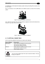
The diagram below represents the termination of a DX6400-XXX-010 working as slave by
means of the BTK-6000 terminator.
Slave
BTK-6000 Male Side
8
7
8
7
LON A
LON B
T
= male connector
= female connector
Figure 29 – DX6400-XXX-010 Slave Termination
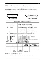
The diagram below represents the connection between a DX6400 Fieldbus model, which
always works as master, and a DX6400-XXX-010 working as a slave reader.
Fieldbus Master
8
Slave
3
7
5
4
3
5
4
VS_I/O
REF_I/O
9
1
2
8
7
9
1
2
LON A
LON B
VS
GND
AWG 16
AWG 16
T
= male connector
= female connector
CHASSIS
CHASSIS
Figure 30 – DX6400-XXX-010 Master/Slave Lonworks Connection
The Fieldbus master is internally terminated.
2.3.3 Ethernet
Connector
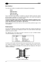
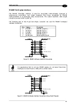
This connector is only available for DX6400 Ethernet models and allows the Ethernet
connection between the host and the reader.
8
1
Figure 31 – Cable RJ45 Male Modular Connector
23
Summary of Contents for DX6400
Page 1: ...DX6400 Reference Manual ...
Page 94: ...www automation datalogic com ...

