Electrical Installation
40
DX8210 Barcode Scanner
Grounding
In order to avoid any problems with electrical noise that could negatively affect
system function, make sure that:
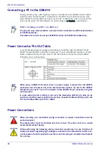
1. The AC power cable coming into the PWR box is always provided with a
Ground and connected to the proper connector (Protective Earth - PE).
2. The structure where the readers, controllers, encoders/tachometers, and
photoelectric sensors are mounted is grounded to the conveyor or to the PE
terminal inside the PWR.
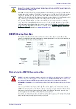
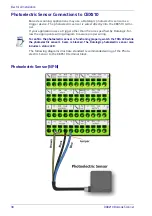
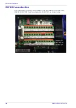
3. The Shield wires from the Encoder/Tachometer and photoelectric sensor
cables are connected to the proper
Shield
terminal in the CBX box.
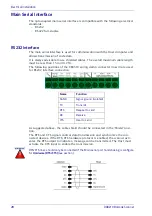
4. Normally, steps 1 through 3 will guarantee proper function. In case of
problems such as transmission of strange or wrong characters, devices stop
working without any reason, or other unexpected behavior, try connecting
the CBX or Controller Earth terminal to the PE terminal inside the PWR box.
Summary of Contents for DX8210
Page 1: ...DX8210 Reference Manual Omnidirectional Barcode Scanner ...
Page 31: ...Installation Reference Manual 19 Small Side Mounted L Bracket Options ...
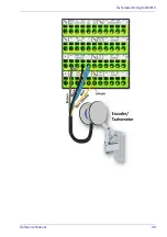
Page 45: ...Tachometer Wiring to CBX510 Reference Manual 33 ...
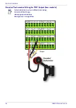
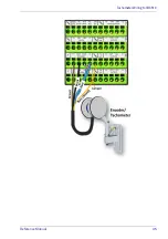
Page 47: ...Tachometer Wiring to CBX510 Reference Manual 35 ...
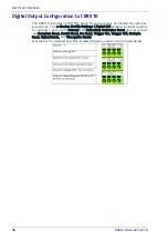
Page 49: ...Digital Output Configuration to CBX510 Reference Manual 37 Unpowered Outputs Powered Outputs ...
Page 268: ...Barcode Scanning Features 256 DX8210 Barcode Scanner DX8210 2100 0 25 mm 10mil ...
Page 269: ...Reading Diagrams Reference Manual 257 DX8210 2100 0 30 mm 12mil ...
Page 270: ...Barcode Scanning Features 258 DX8210 Barcode Scanner DX8210 2100 0 38 mm 15mil ...
Page 271: ...Reading Diagrams Reference Manual 259 DX8210 2100 0 50 mm 20 mil ...
Page 272: ...Barcode Scanning Features 260 DX8210 Barcode Scanner DX8210 4100 0 38 mm 15 mil ...
Page 273: ...Reading Diagrams Reference Manual 261 DX8210 4100 0 50 mm 20 mil ...
Page 274: ...Barcode Scanning Features 262 DX8210 Barcode Scanner DX8210 4200 0 25 mm 10 mil ...
Page 275: ...Reading Diagrams Reference Manual 263 DX8210 4200 0 30 mm 12 mil ...
Page 297: ...Reference Manual 285 ...
Page 298: ......
Page 299: ......

